Topic: Examining and repairing a complete JOLT system
Date: 2026 AUG 04
As mentioned in the MAI 8080A/9080A System Card writeup, I’ve been searching for a JOLT system since Bill Degnan had gotten out his MAI Jolt 6502 SBC at one of the workshops he hosted in the 2010s. When I got a saved search alert in July 2026, I was a little more careful with my inspection of the listing this time! It was in fact a listing for a 6502-based JOLT, and not just the SBC but a “Powered JOLT 4K System” configuration. This is what I received:
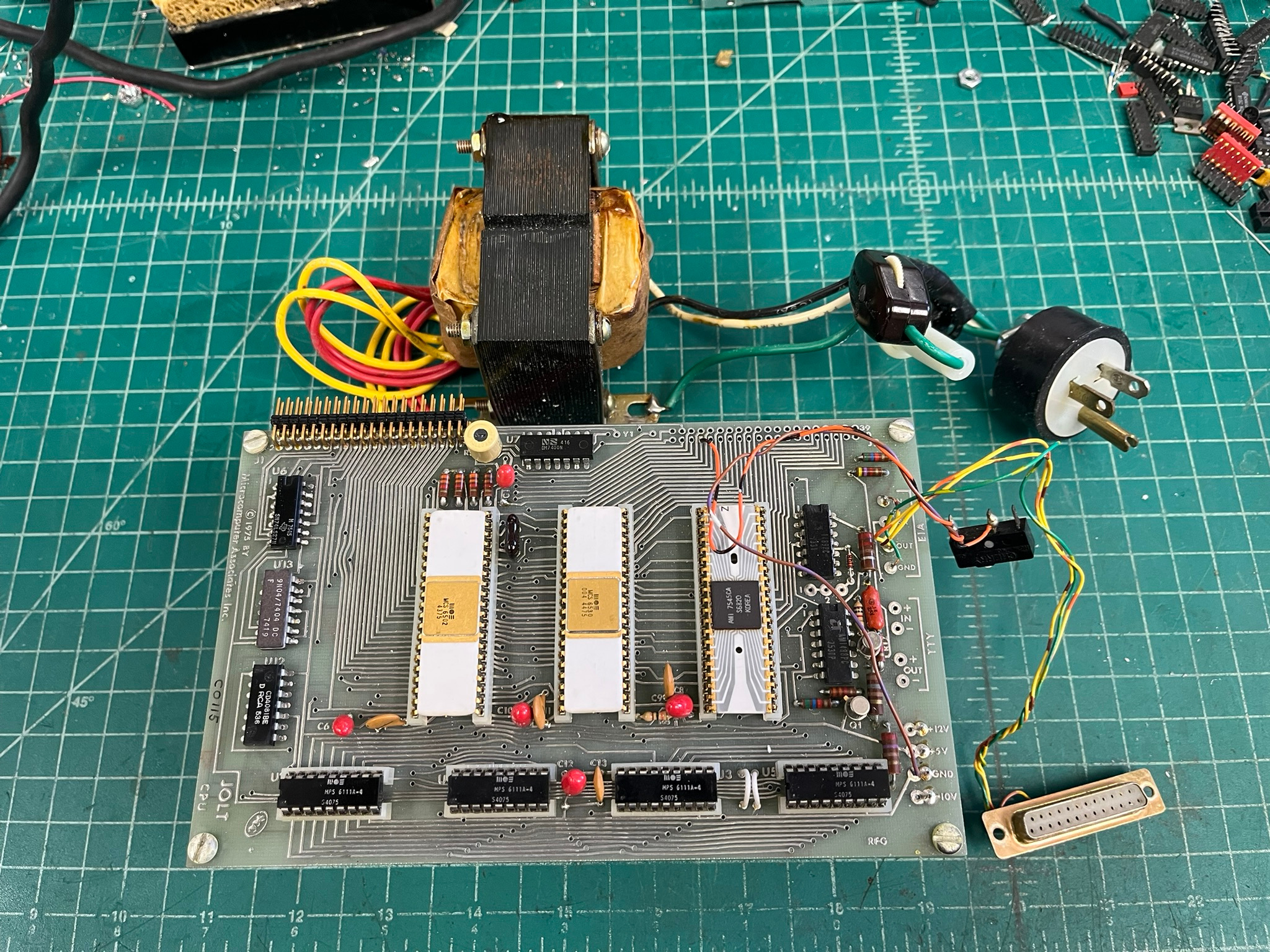
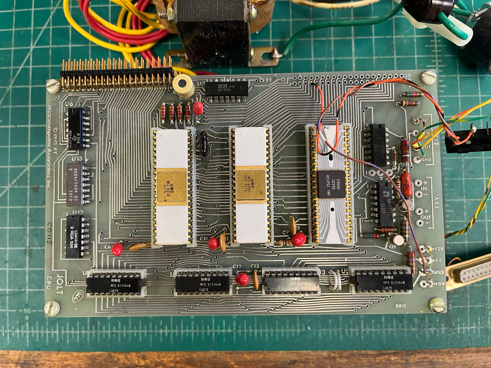
Since the system stacks, it’s not really clear what else is there, other than the power transformer, from the above pictures. Here’s a shot from the side:
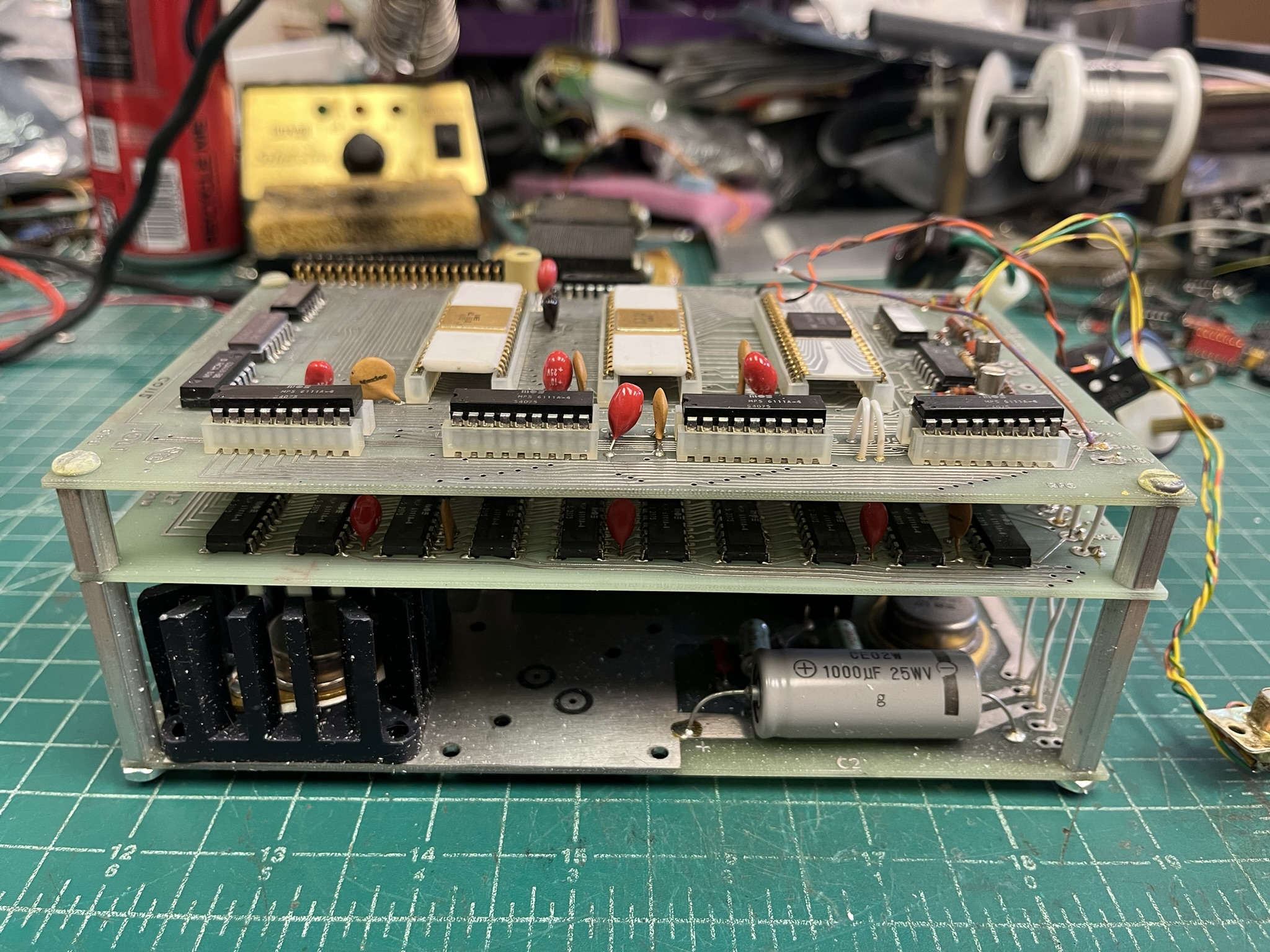
Unlike the 8080A System Card, this MAI product appeared to have been actually used. There’s wiring for a RS-232 console connection, and a reset switch hung off on flywires. The lot was really complete, let’s take a look at some of the items that came with it!
Initial Unpacking and Assessment
The Powered JOLT 4K System (“the System”) came in some vintage/original packing, fortunately overboxed by the seller for shipping. This was the outer box:
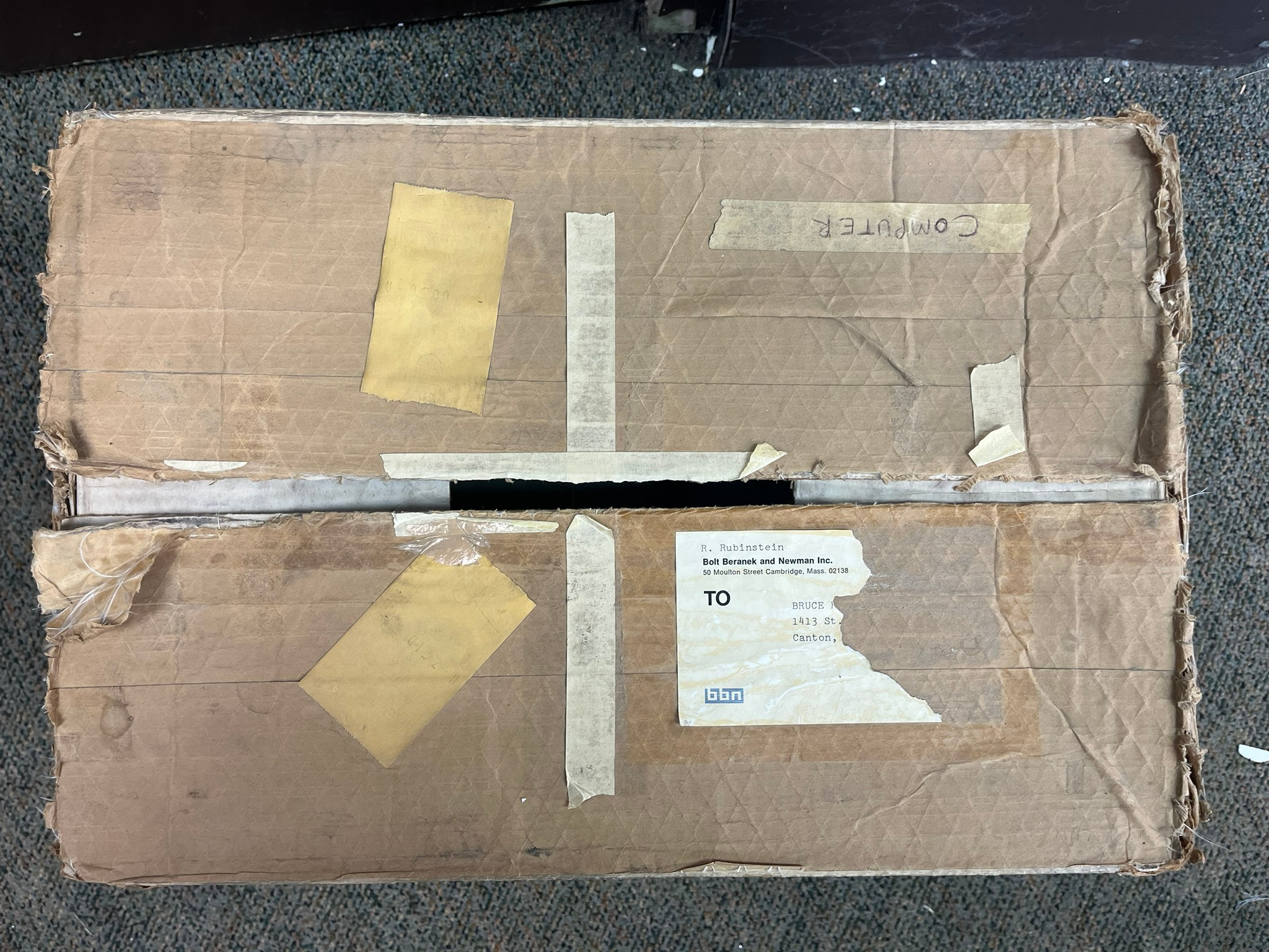
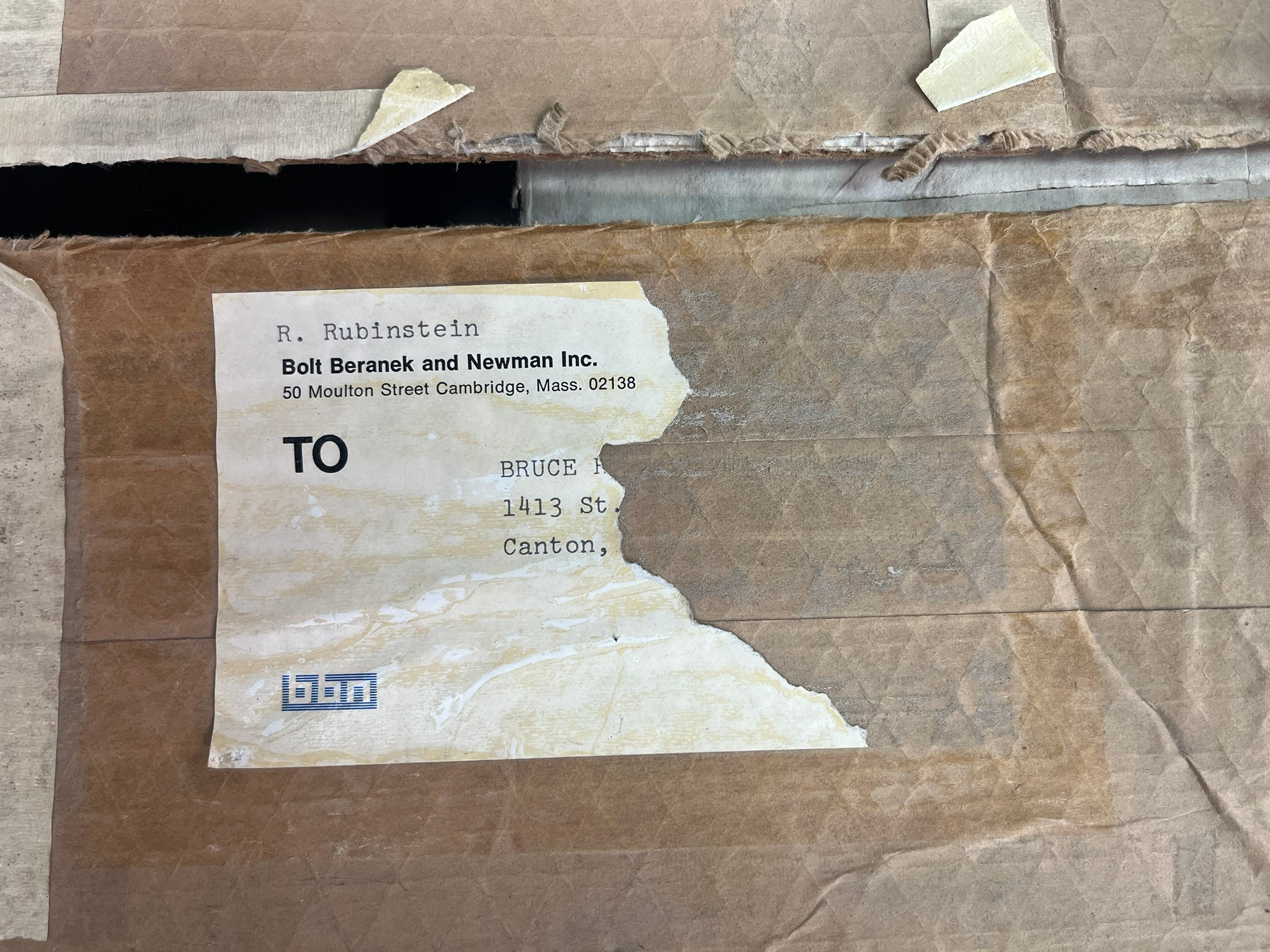
The label on the outer box suggests it was shipped from Bolt Beranek and Newman Inc., a fairly significant MIT-adjacent tech consulting company that has since been rolled into Raytheon (now called RTX Corporation). R. Rubinstein turns up a few results regarding technology papers written on behalf of BBN, but I haven’t dug further. Too bad we don’t have more of the addressee portion of the label!
UPDATE!
ats on #vc IRC (irc.slashnet.org) has turned up information on the recipient based on the partial address. a Bruce R. Meadows, callsign WB8LYK, at 1413 St Elmo NE, Canton, OH 44705 shows up in a listing of amateur radio stations in Stark County. Good sleuthing!
The outer box has some orange lettering that matches the font and color of one of the inner boxes, which is definitely from MAI directly:
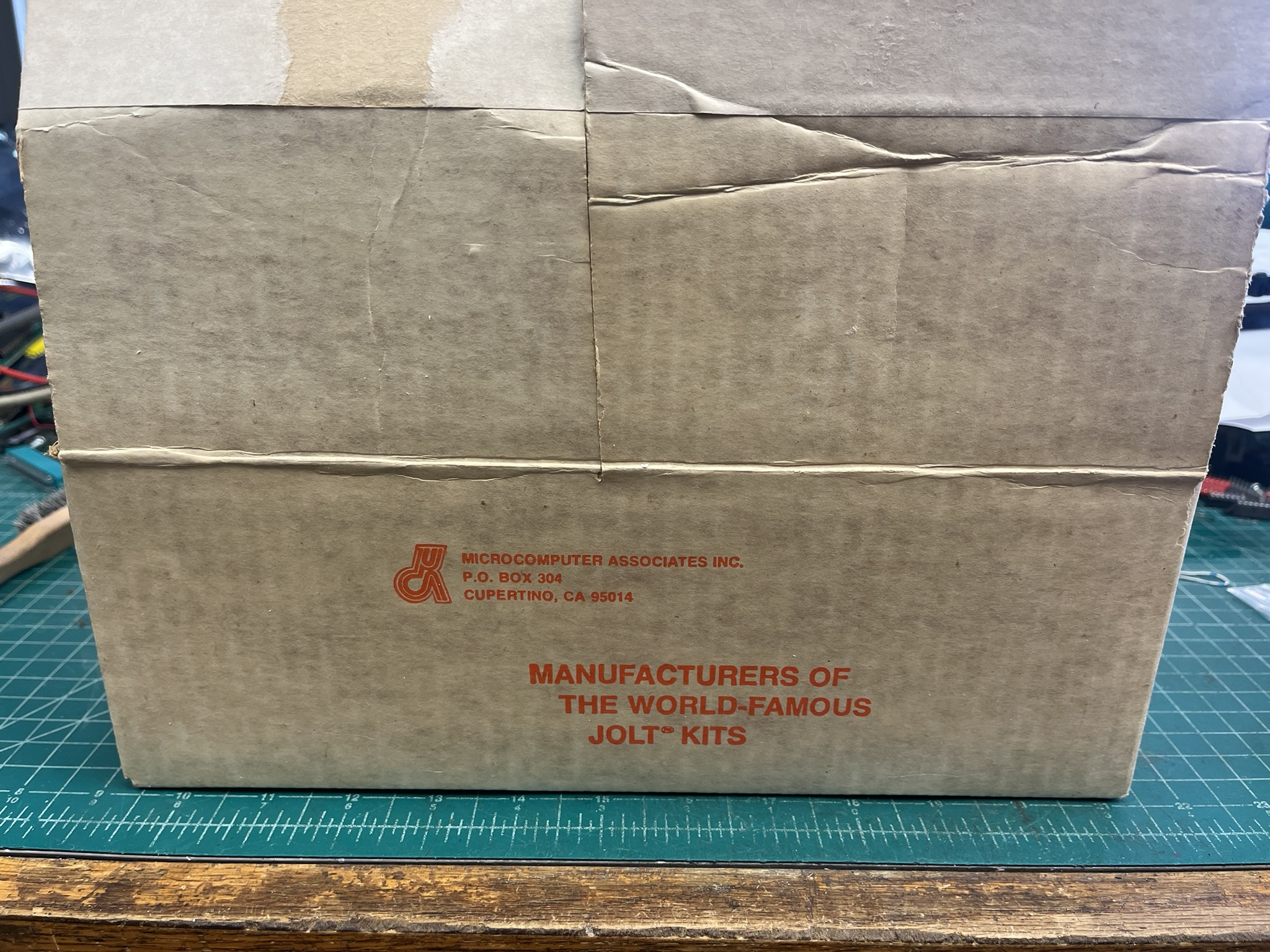
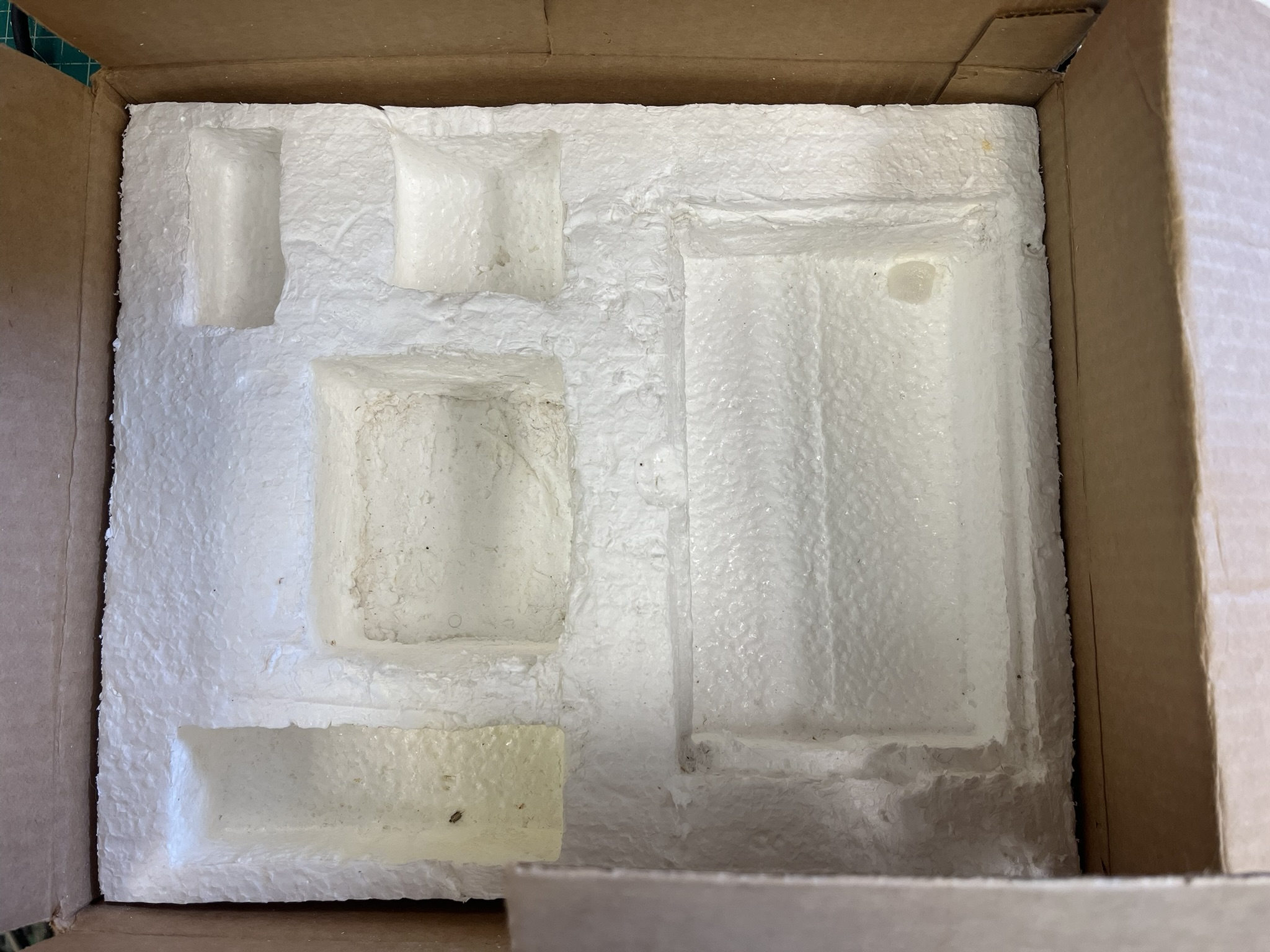
I think the above MAI shipping box is actually for the power supply option, from the cutouts in the foam insert. It’s in pretty good shape, but the top flaps have been cut for some reason. I’m not a box-saver, but this one won’t be thrown out.
Aside from the above System assembly, there was a partial JOLT accessory bag:
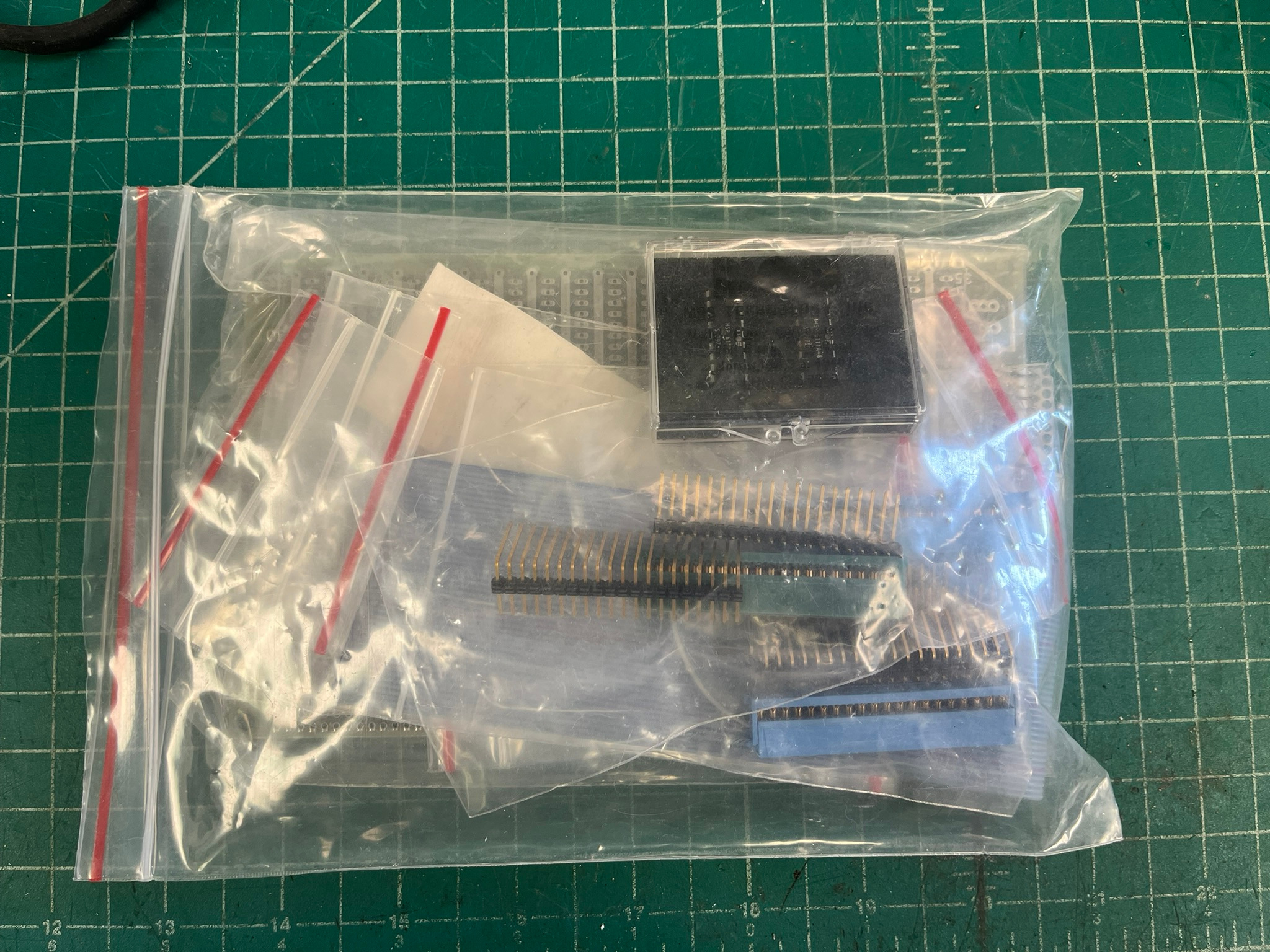
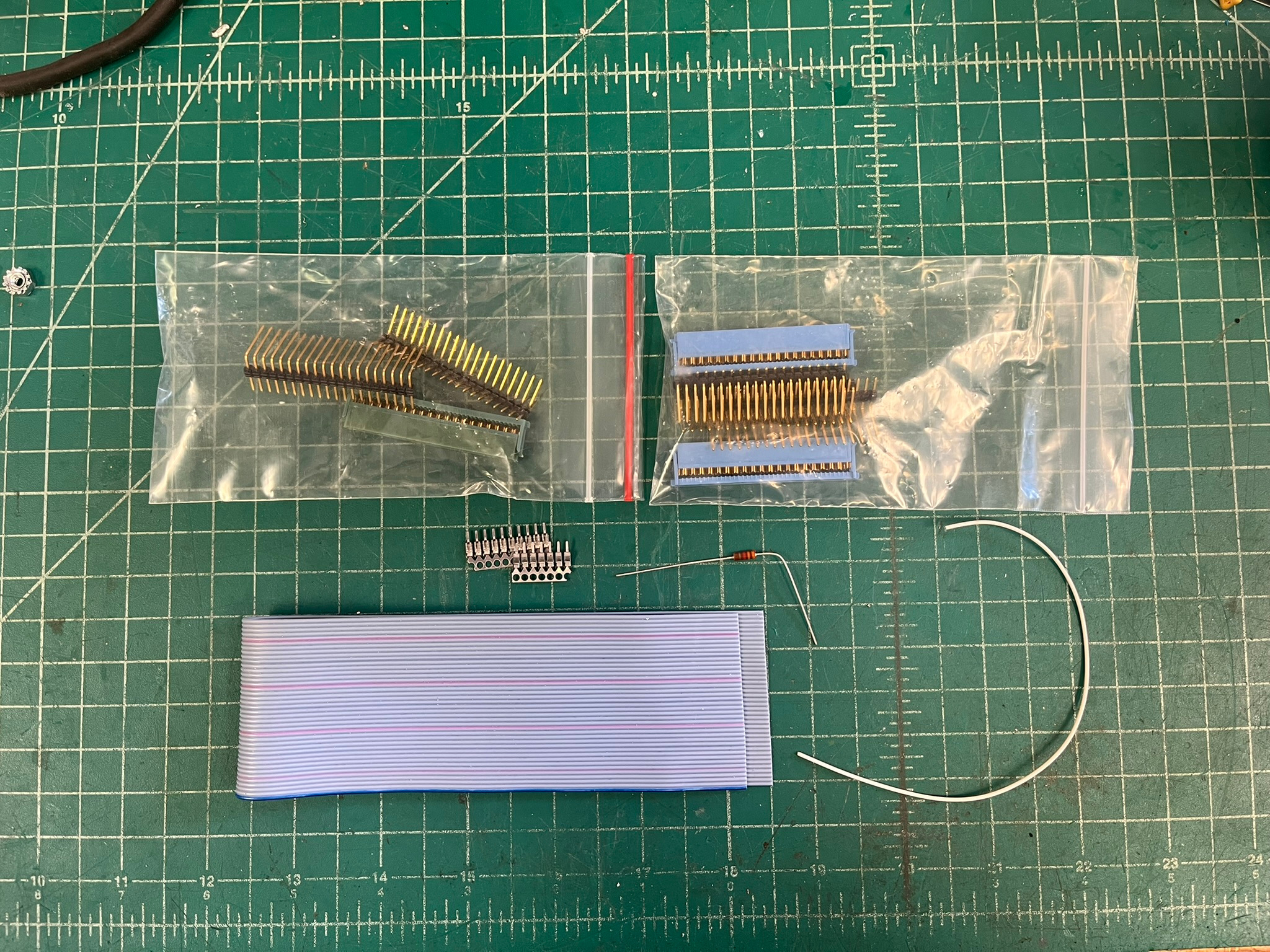
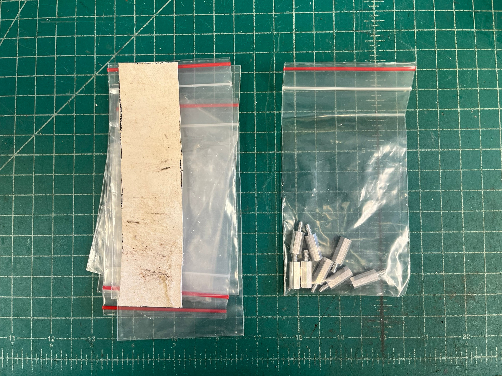
The bag is missing some pieces, which were probably used in assembling the System, but also includes some extras. Here’s a look at the miscellaneous small parts:
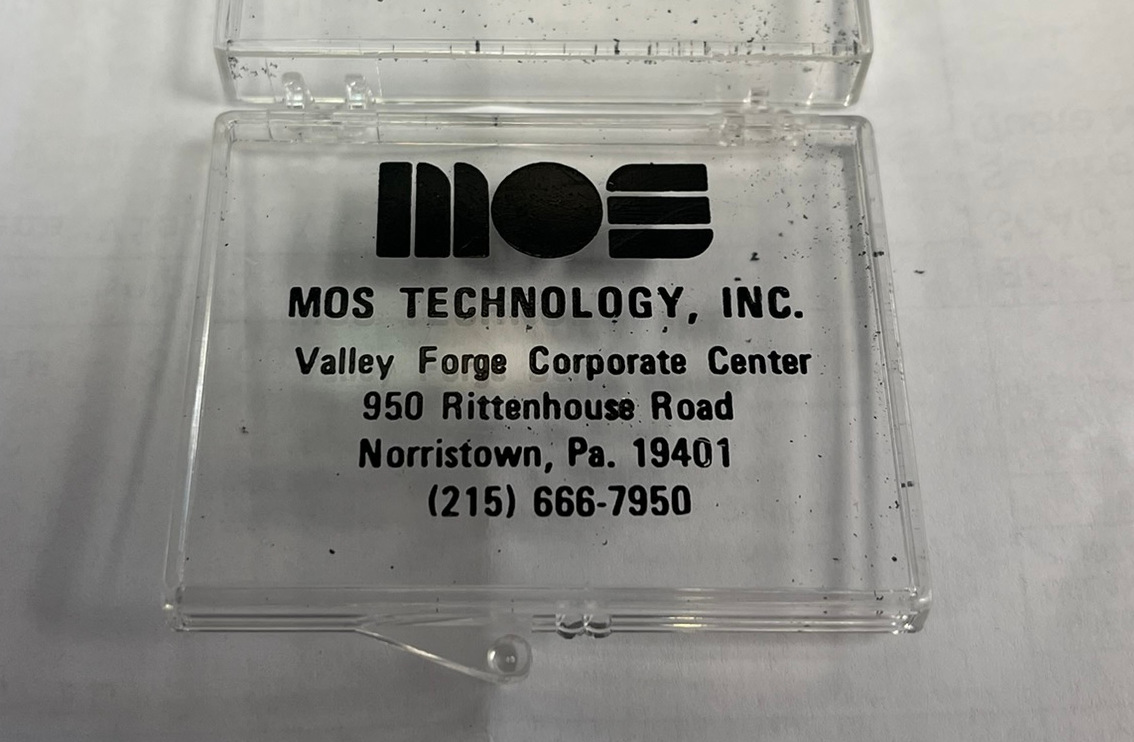
There was also this neat MOS branded plastic box, which contained two MOS 6111A static RAM chips:
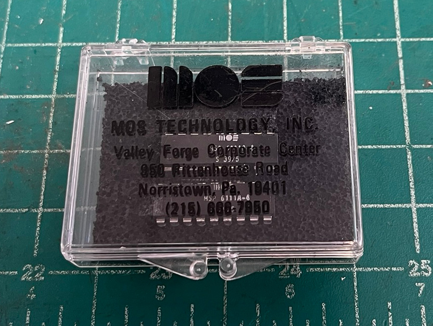
The foam in the MOS box was starting to degrade, but had only lightly stuck to the ICs’ legs. The foam was removed, the ICs wire brushed to remove the bits that hung on, and new foam was cut from insertion grade stock.
There was also an unused “JOLT Universal” prototyping card, in the original plastic bag:
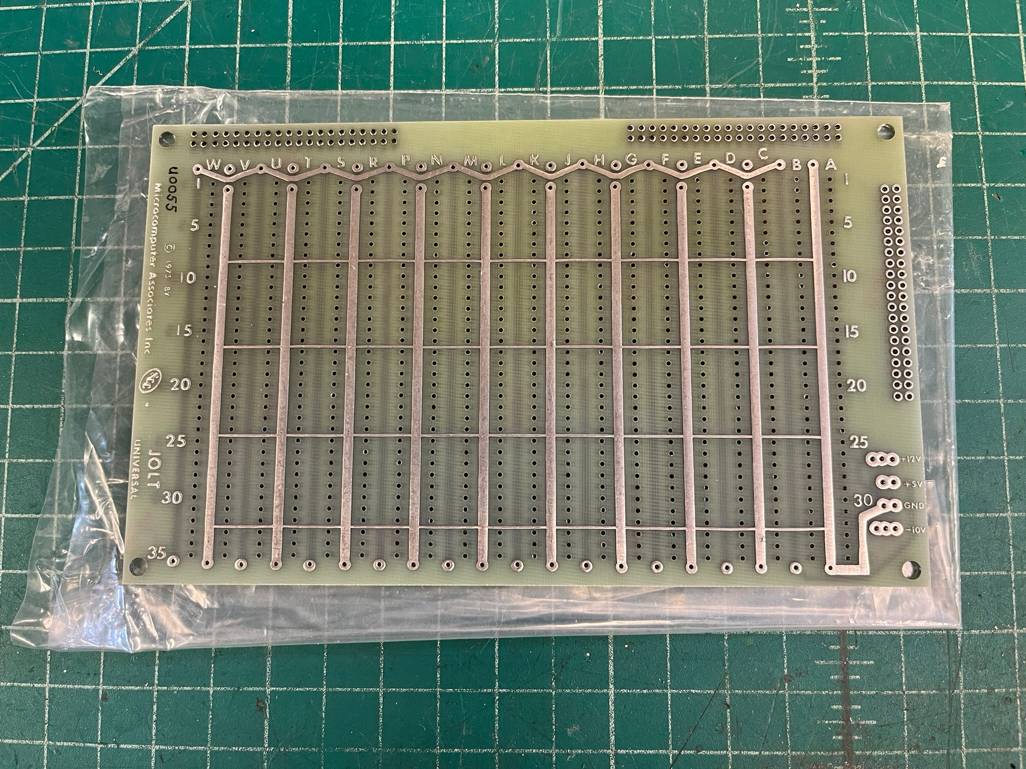
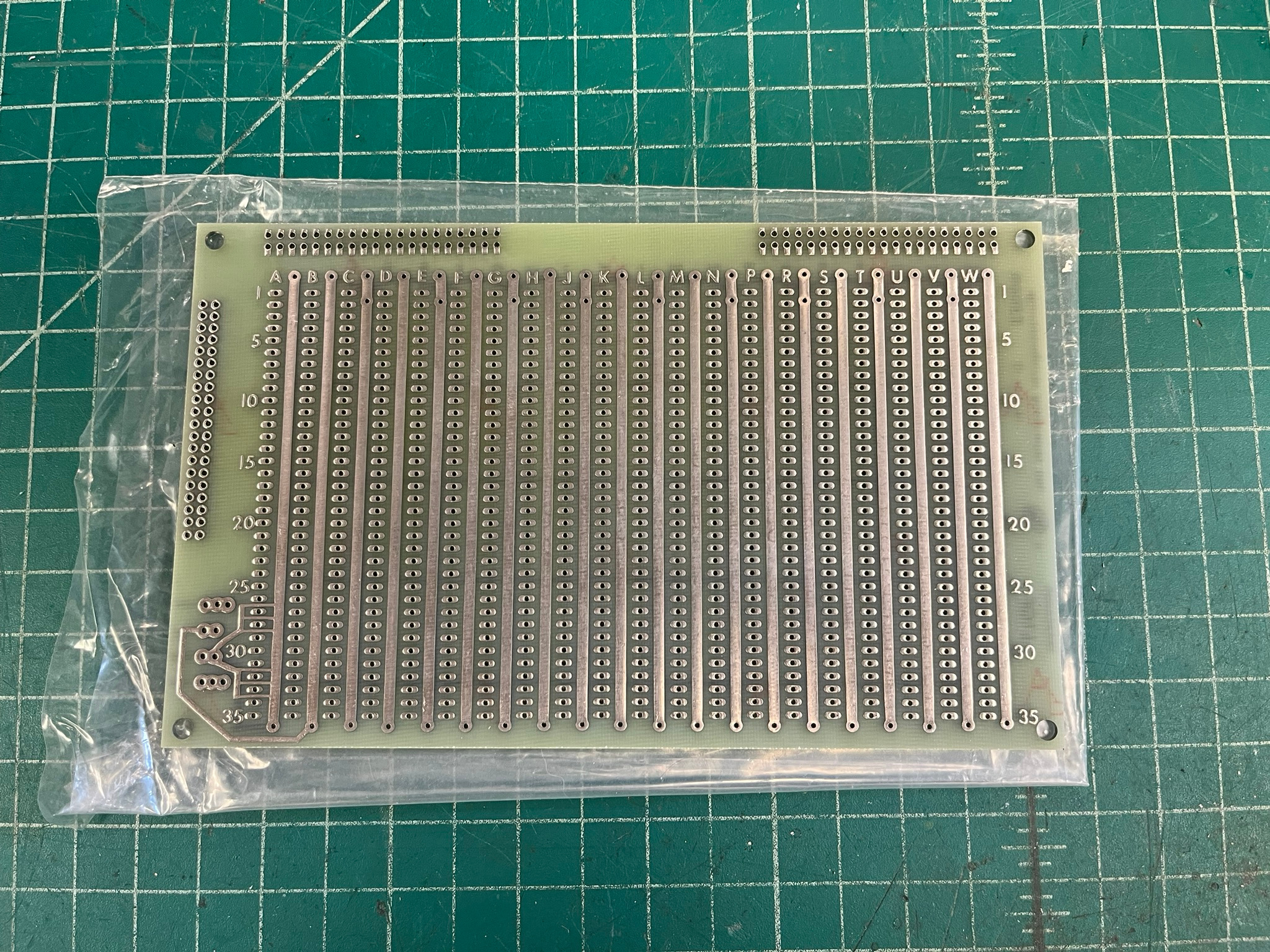
Aside from MAI hardware, there’s also a PAIA Electronics PVI-1 video interface kit, which has been partially assembled:
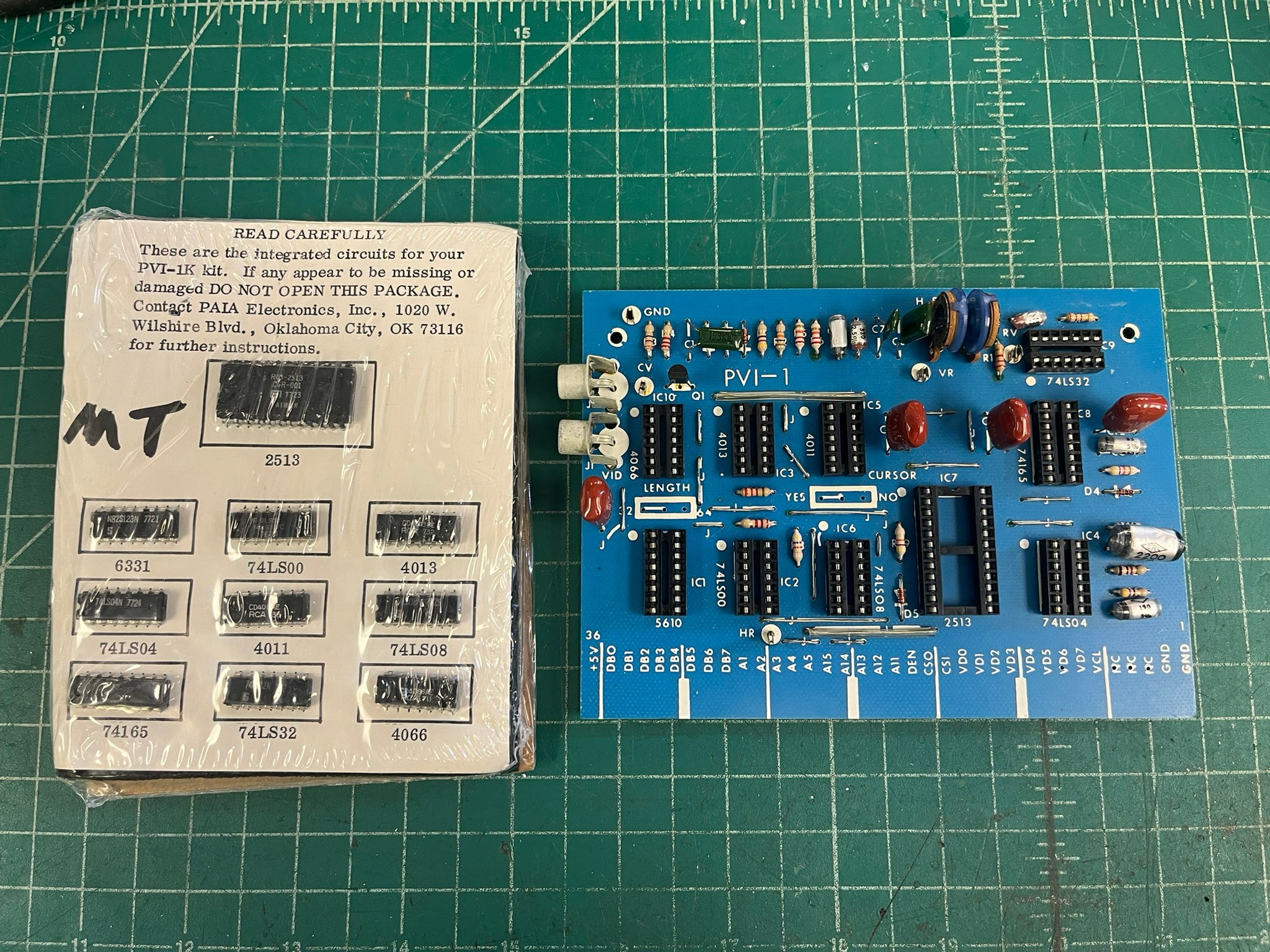
From reading, the PVI-1 appears to be a 100% direct copy of the Don Lancaster TVT-6 TV Typewriter circuit board. It provides some of the hardware necessary to create a video interface for a system, the rest is done with some of the host’s hardware (memory, mostly) and software assistance.
Unfortunately, there was no documentation included with the System.
System Stack Disassembly
To work on the System, it was going to have to be disassembled. There was no way I was about to power up the power supply it came with! The power cord did not inspire confidence:
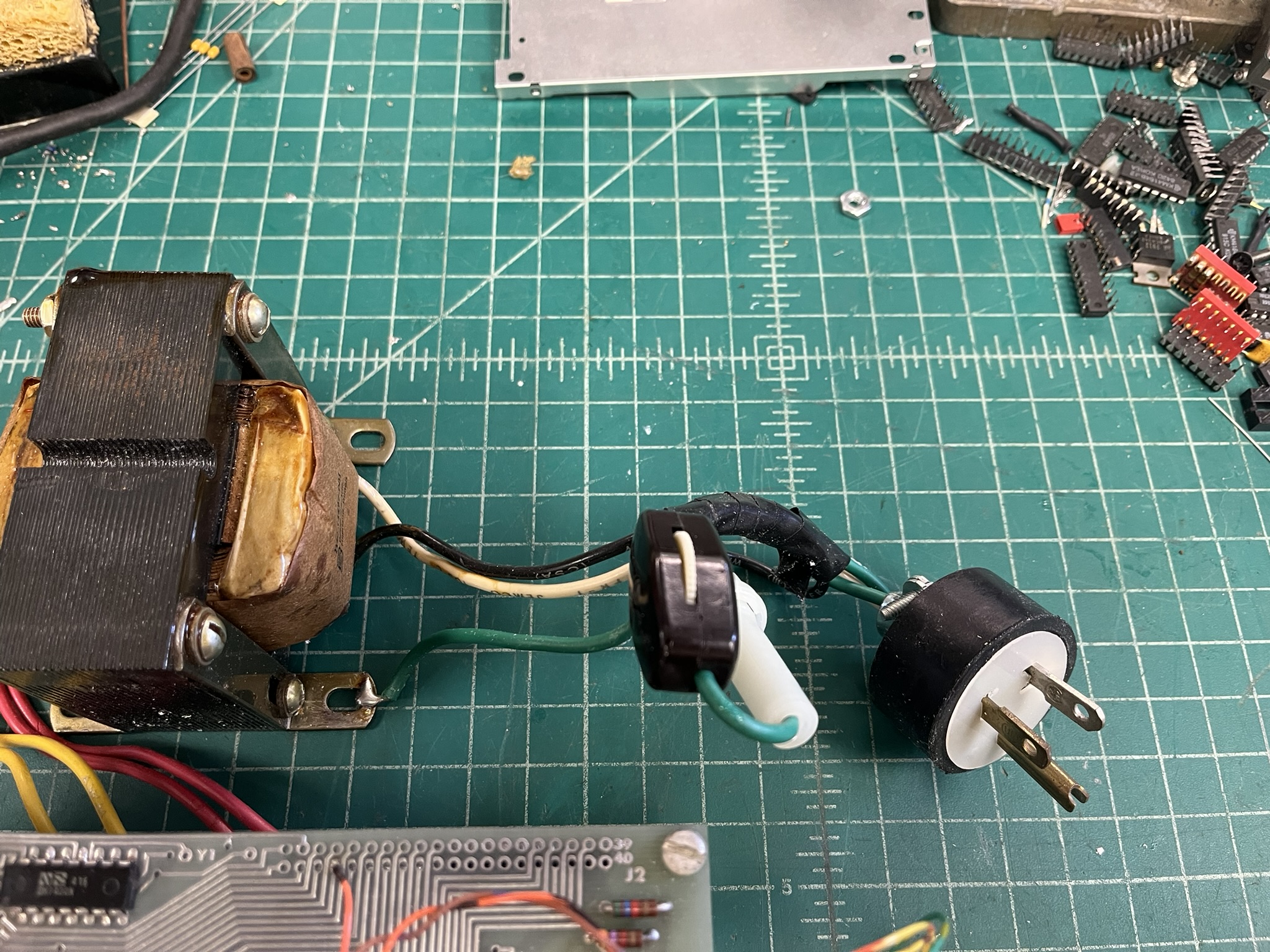
I especially like the green wire carrying phase from the plug to the fuse holder. There was no fuse in the holder, and the non-spring end of the assembly was just the transformer black wire with a big ball of solder on it – no metal contact stamping! I removed the plug and snap switch, discarded the fuse holder, and removed the soldered ground wire from the transformer mounting bracket.
I then separated the boards in the stack, starting with the JOLT itself, of course:
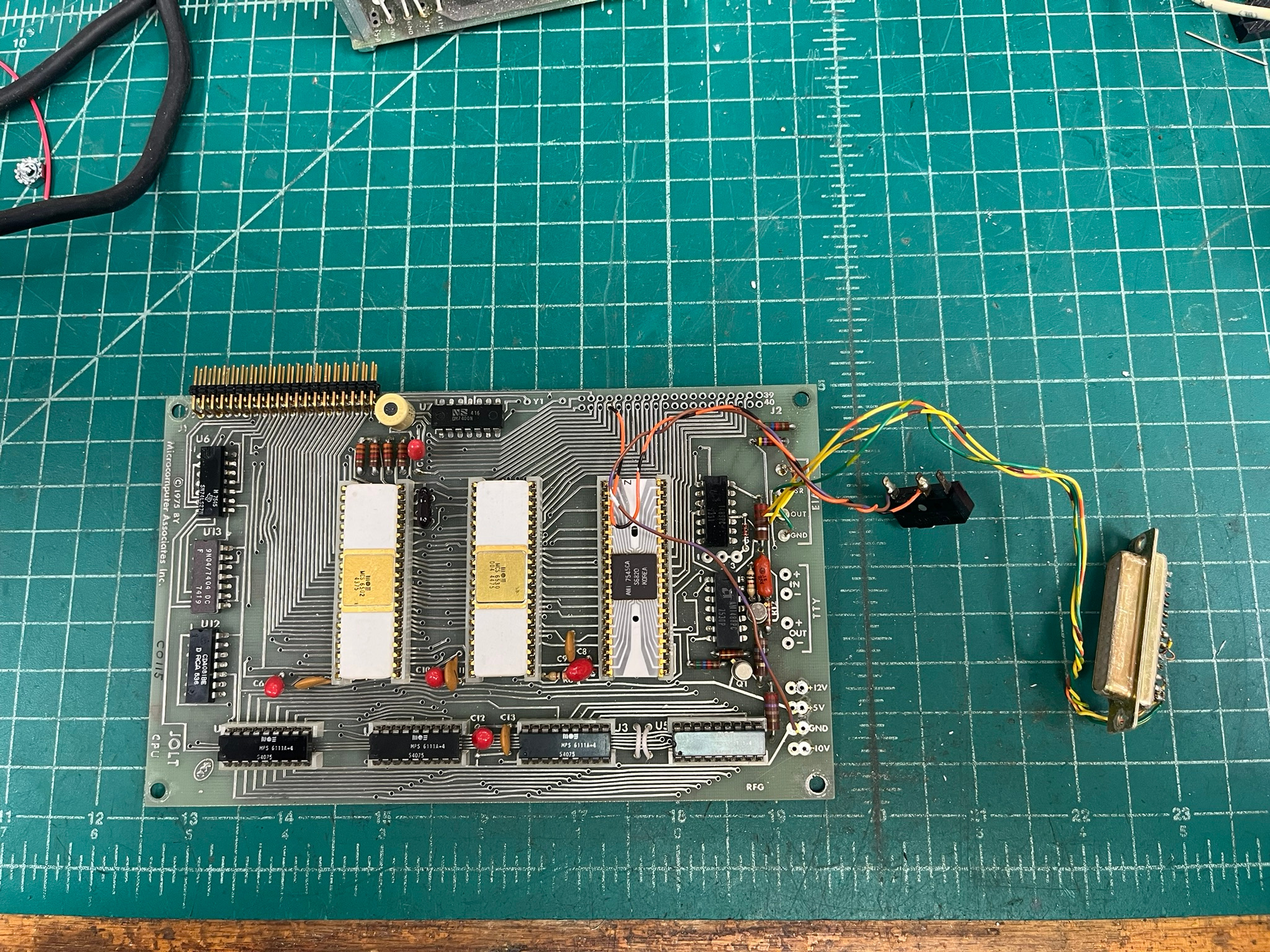
Next in the stack is the 4K RAM board:
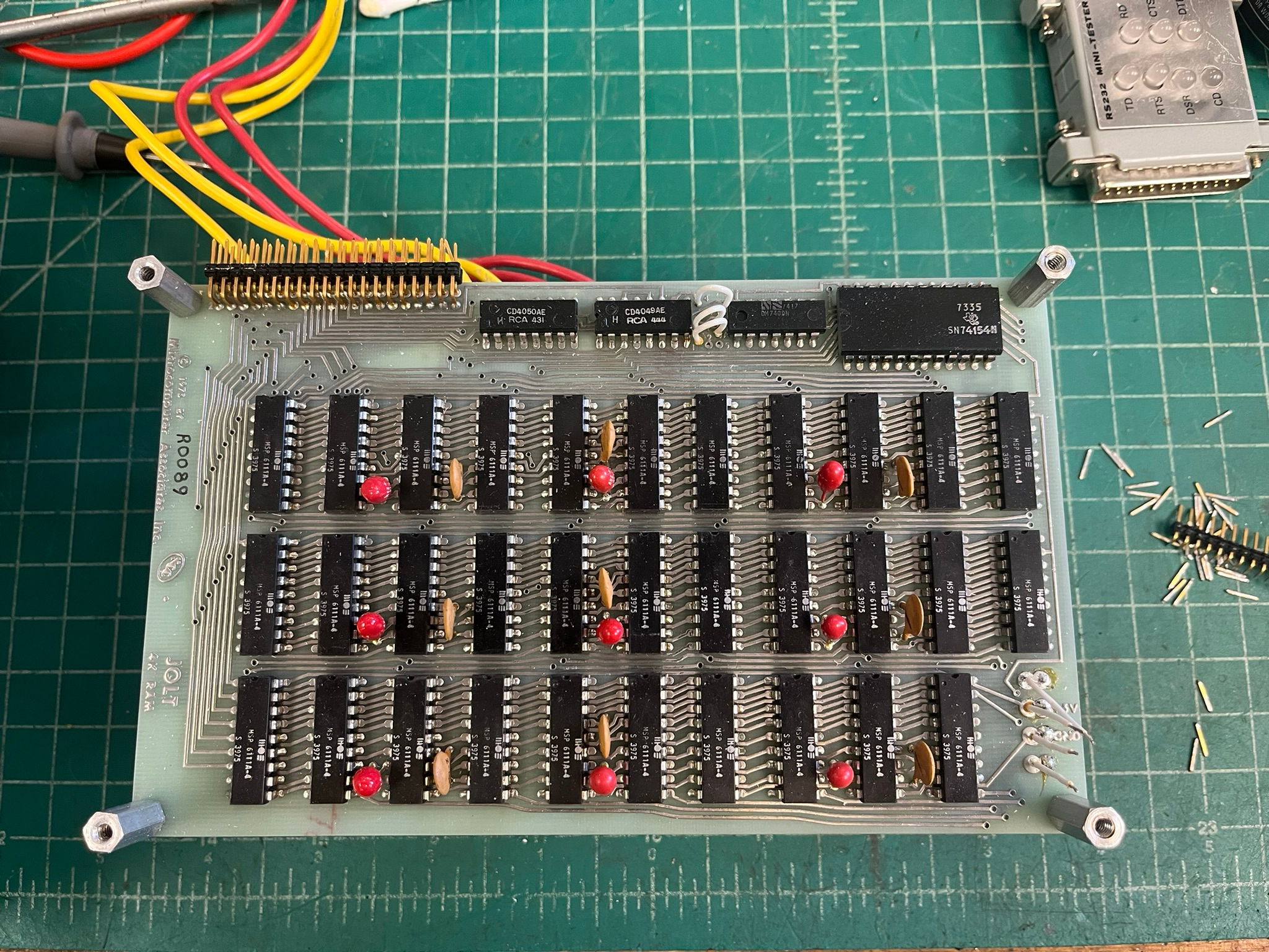
Quite the pile of 256 x 4 static RAM chips!
Under the 4K RAM board is the PSU board, which serves as the “base” of the System:
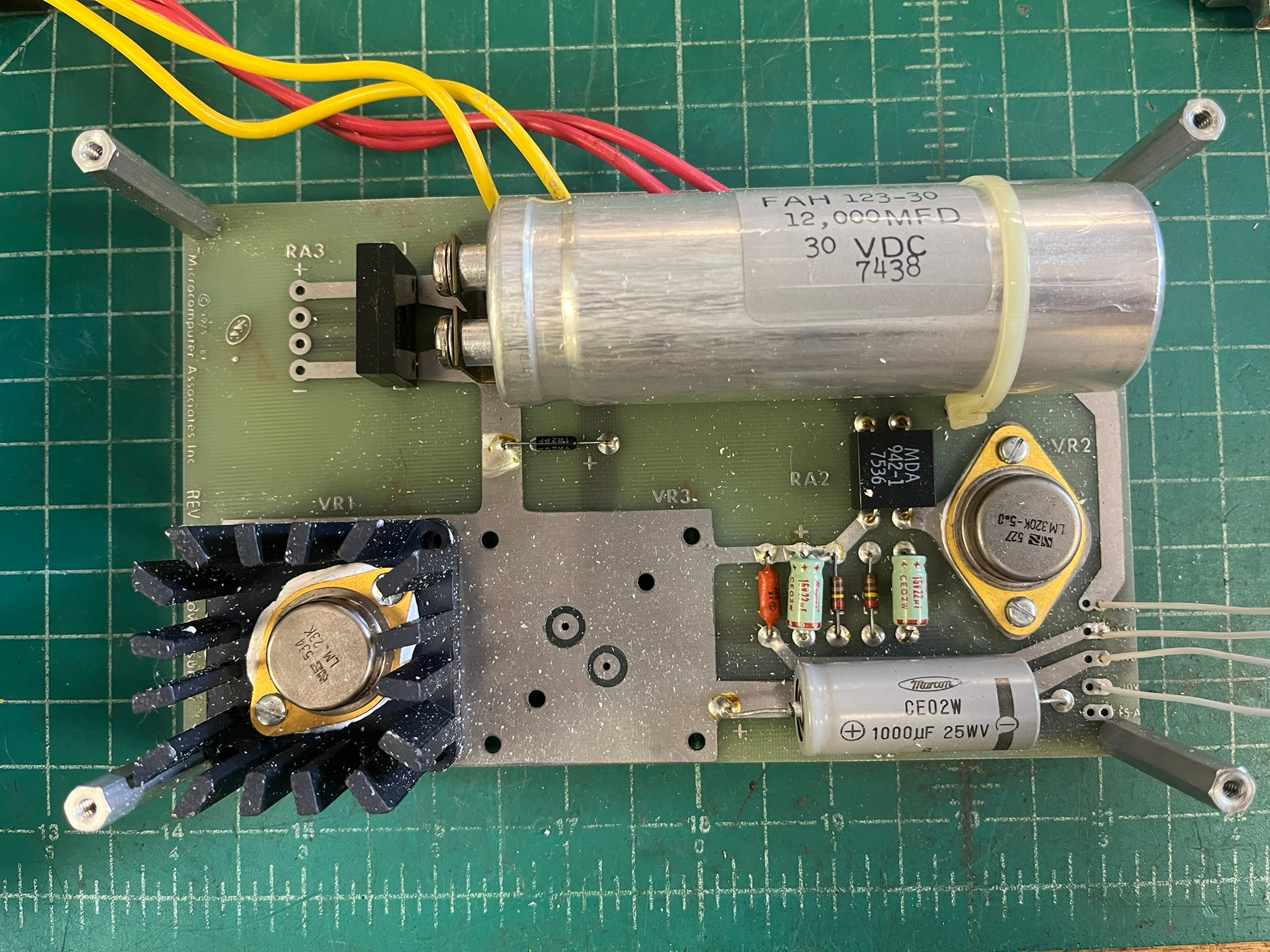
The small capacitors on the PSU board will get replaced, and the large bulk capacitor will get reformed. As long as it reforms and tests fine, it will be safe to use.
Testing the JOLT
With the System separated, I set the JOLT up for testing. I used grab leads and a HP 6235A power supply to get power into the system. The console RS-232 connection was hooked to a PC running a terminal emulator through a RS-232 lights box. Ready to power on:
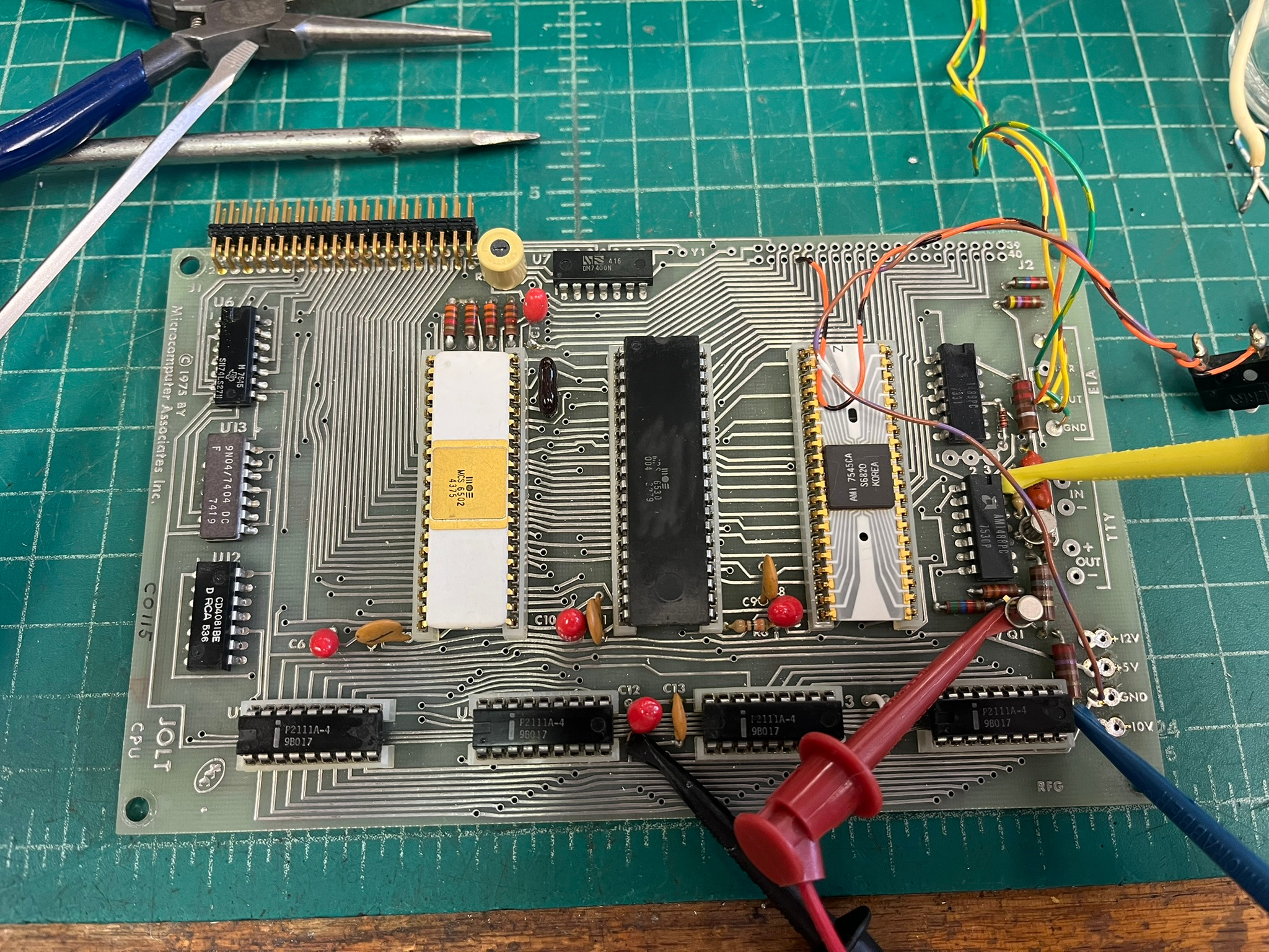
I hit the reset switch, and then hit ENTER on the keyboard. Nothing happened. The above image gives away what the problem was…all four MOS 6111A static RAMs were bad! Fortunately, we stock compatible devices, due to their use in S-100 systems and the Intel SDK-80. With new RAMs installed, the DeMon monitor in the TIM chip signed on. Just to verify that all four of the 6111A SRAMs were dead, I tested them in our test bench SDK-80:
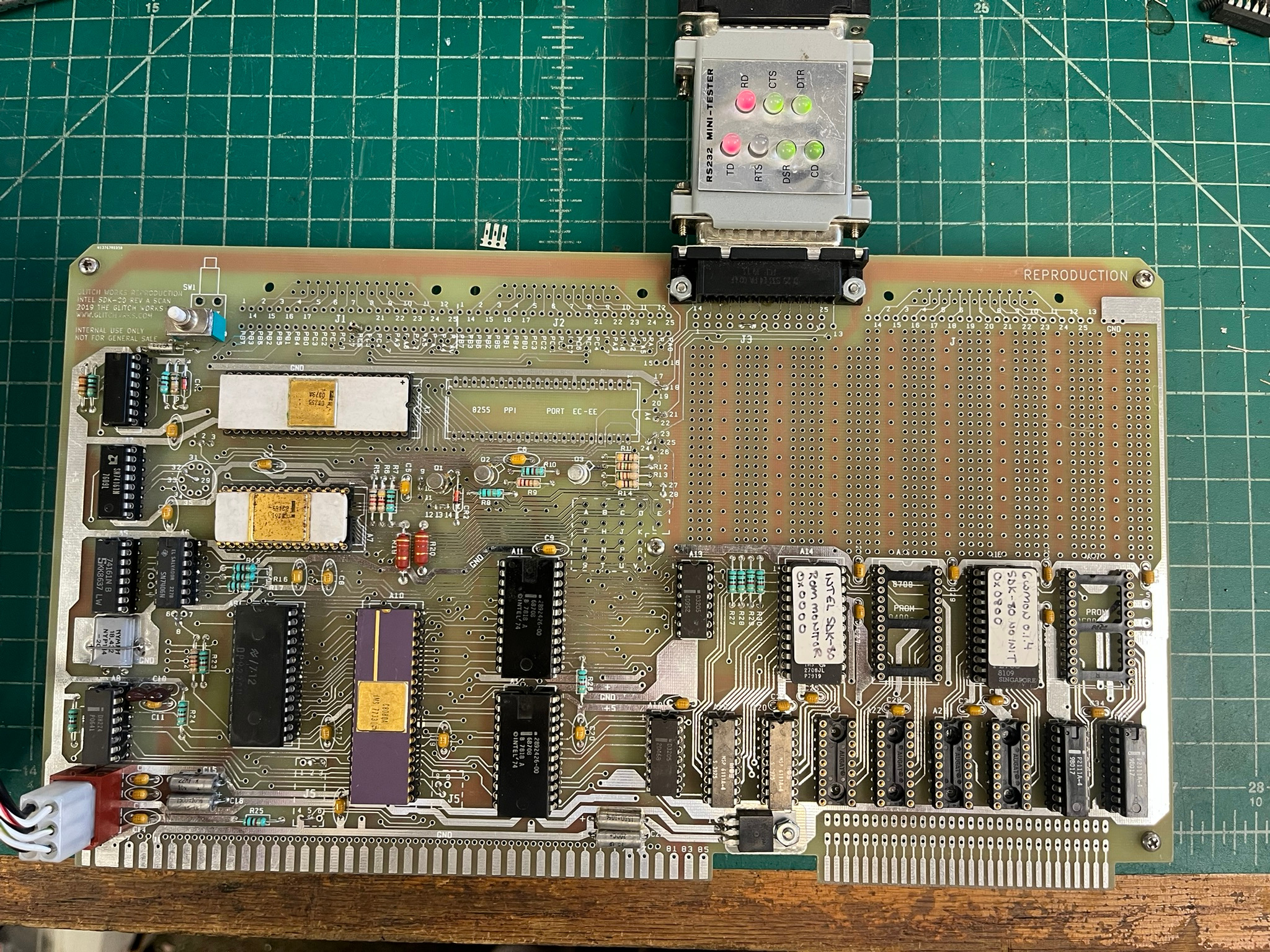
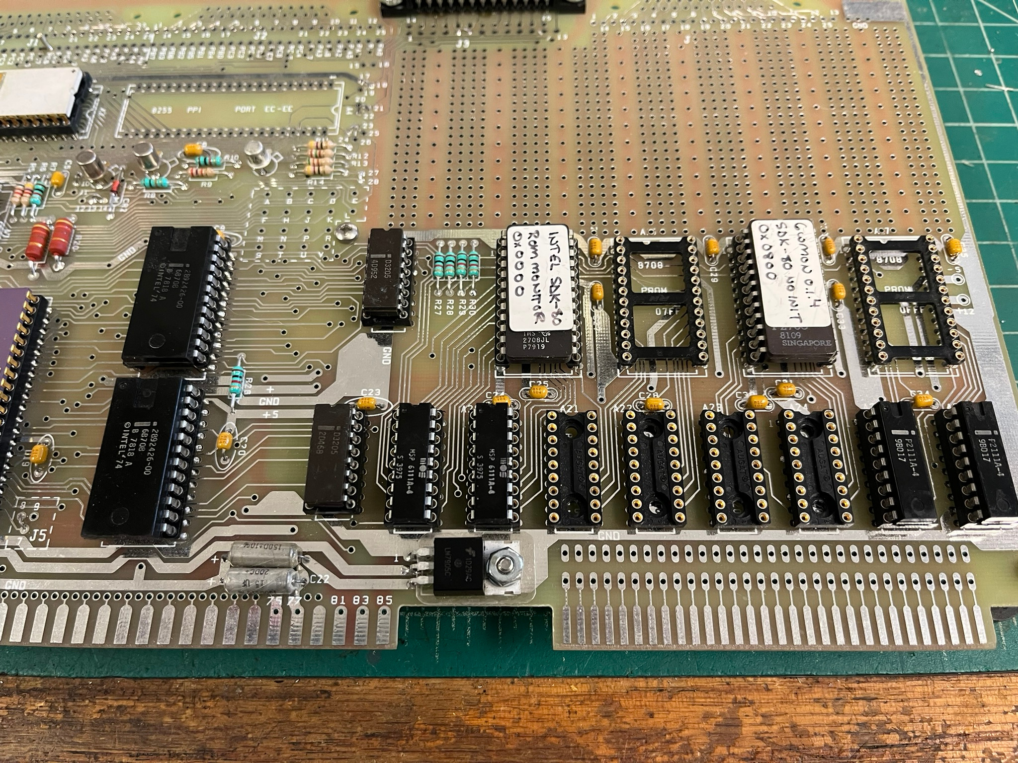
The SDK-80 uses the SRAMs in the rightmost sockets for the monitor stack and variables, so unknown SRAMs can be placed in the other sockets and tested. Two of the MOS 6111As hung the system, the other two didn’t seem to be responding to bus access. I don’t know what happened to them, but the rest of the JOLT is fine!
I ended up removing the pin header from the system connector position as it was wire wrap length on the bottom side. The JOLT now appears like this:

A very good looking board! I’ll have to see about finding some MOS 6111As to go into it.
Side-Quest: TIM Testing and 6502 Repair
As seen above, there’s a black MOS TIM 6530-004 installed in the JOLT from one of the testing pictures. This is a part I’d bought on a popular Internet auction site, with the intention of putting on an Ohio Scientific 400 Superboard. The ROM and RAM sections are definitely fine, but I have not fully tested the I/O section.
While I was testing other chips in the JOLT, I got out a damaged 6502 to repair. This one was traded to me by Jeff Galinat, in exchange for some S-100 repair work:
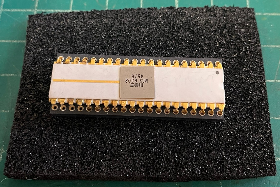
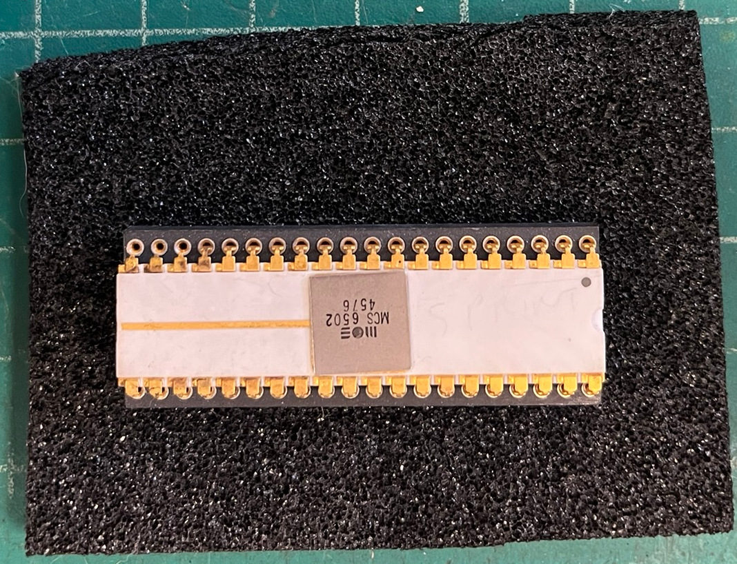
This early 6502 suffered leg rot as many old ICs do: black antistatic conductive foam had broken down and rusted seven legs off. My usual repair on brazed leg packages is to cut down some Batten & Allen leadframe pins, cut down the stubs on the IC package, and solder them on. With side-brazed DIPs, you then cut them to length. With this style of package, the Batten & Allen pins have to then be carefully folded down. I generally start the bend with pliers, but finish with finger pressure, so as not to risk lifting the pads on the DIP package. Here they are, soldered down, but not yet bent:
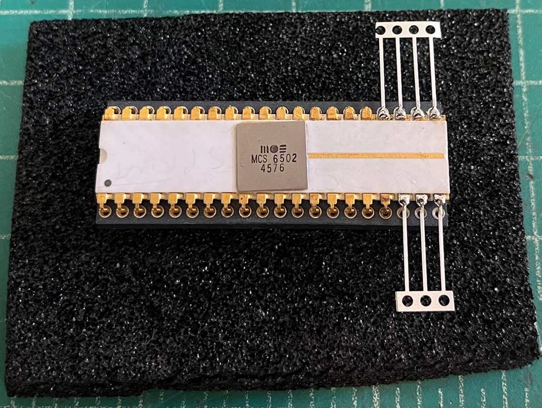
Success! The 6502 works fine, and appears to be post ROR bug fix.
Future Hacking
For now, the Powered JOLT 4K System had to be cleared from the bench for other work. I intend to mount it on a Bud box, with the power transformer in the bottom, and a more serviceable power distribution setup.
Hopefully, the 4K RAM expansion isn’t full of also-dead 6111A chips! The two in the plastic MOS box tested fine in both the SDK-80 and the JOLT, so there is hope. Every single one of them is soldered, and there’s 32 of them, which will eat a lot of our 2111 SRAM inventory.
I may do a reproduction of the “JOLT Universal” prototype board, rather than build up the original. Let me know if you are interested in one!
I am still hunting for a Super JOLT, or any of the add-on cards produced for the series. Please message me if you have something you want to part with – especially if there’s documentation available!
bad RAM chips replaced