Topic: Fixing a floppy controller, building a second C3
Date: 2019 JUL 30
When I started into the repairs that are documented in this writeup, I’d originally intended only to repair the OSI 470 floppy controller that originally went with my Challenger III C3-OEM system. Until now, the C3-OEM system was running with an OSI 470 controller acquired with another system. The board that came with the C3-OEM was an older no-rev 470, while the borrowed board was a 470 rev B with the RTC/timer interrupt circuitry populated for use with OS-65U. The borrowed board had “just worked” and so the original OSI 470 sat in the box of spare boards until last week. It’s a simple board, how hard of a repair could it be?!
Initial Check-Out and Cleanup
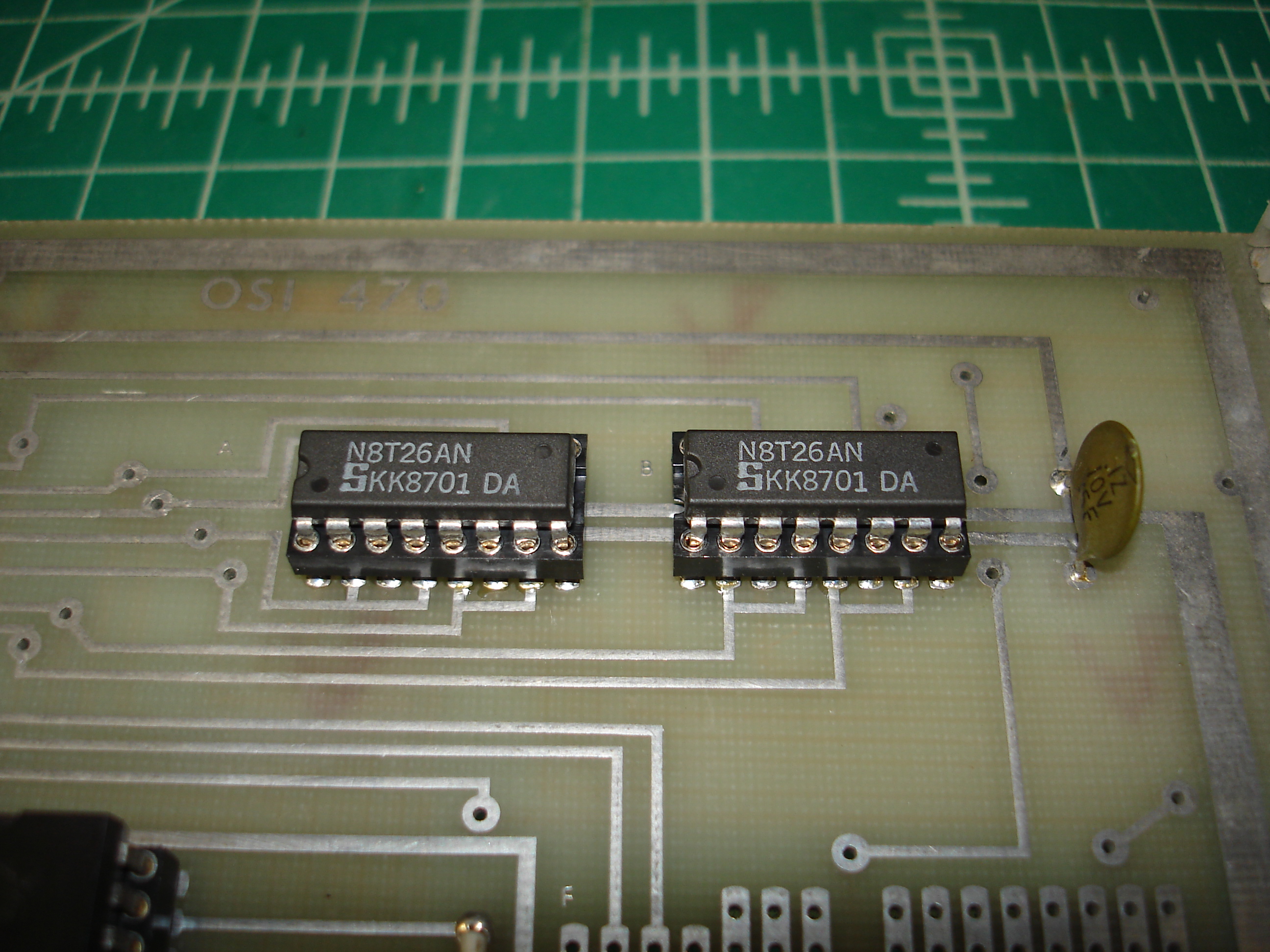
This 470 board had a fair bit of pin rot: many of the original ICs were Texas Instruments chips with silver-plated legs, which had succumbed to oxidization. The two 74123 dual multivibrator ICs got the worst of it, with both originals leaving some legs in their sockets. The sockets were not of particularly high quality, with the 40-pin and 24-pin sockets being single wipe and somewhat corroded. Additionally, the board had its 8T26 bus transceivers stolen at some point during my ownership.
All of the IC sockets were removed and replace with high quality machine pin sockets:
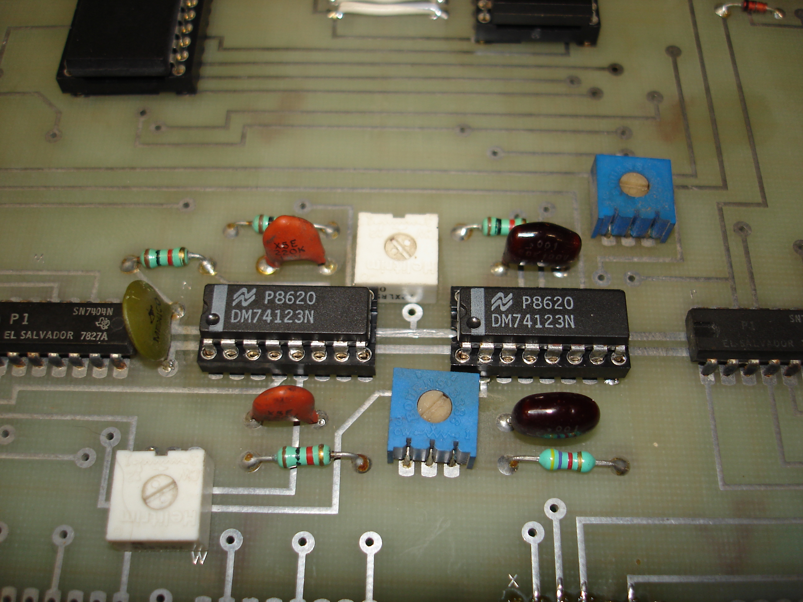
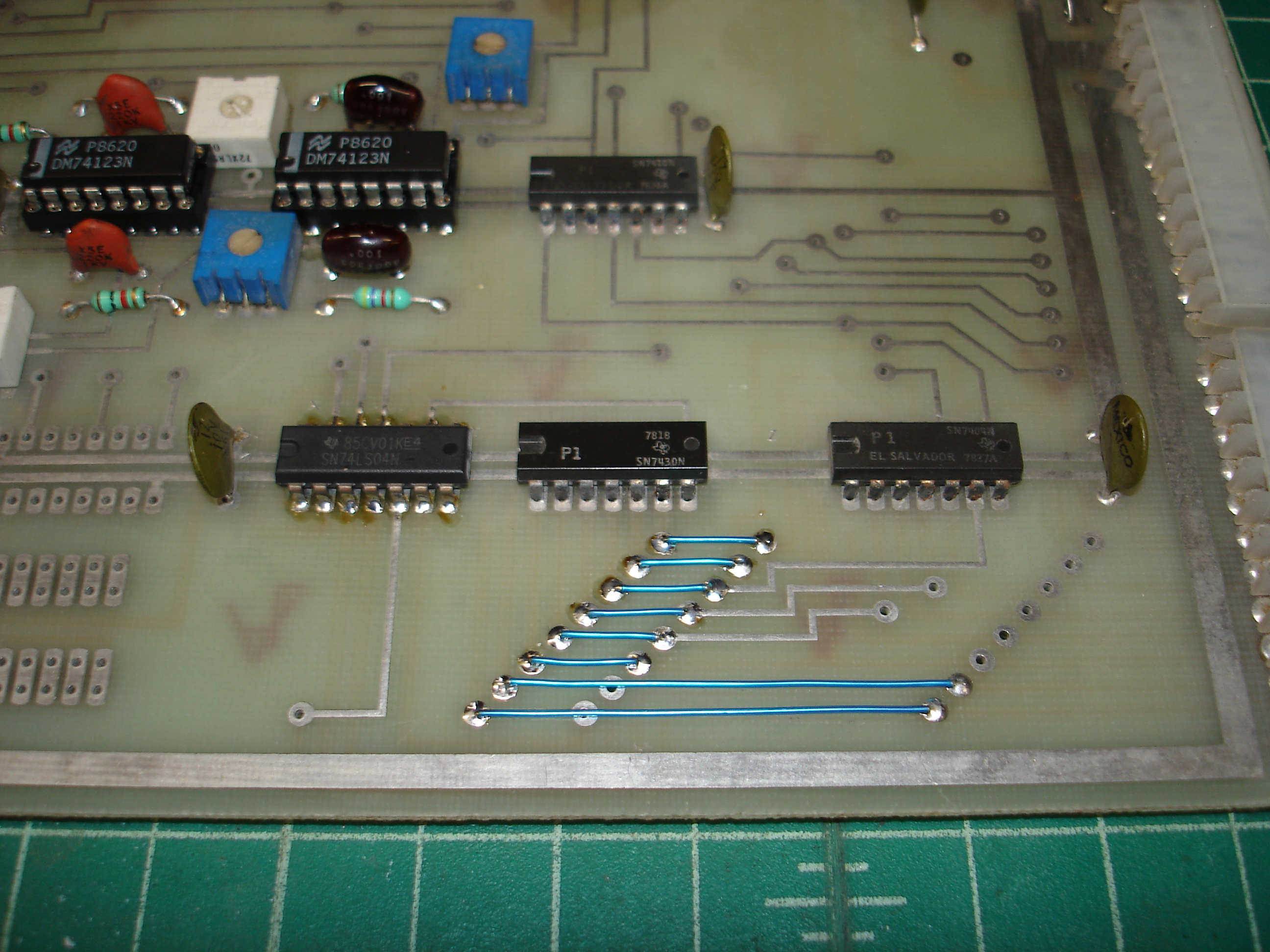
Since the board was on the repair bench anyway, both electrolytic capacitors were replaced - they were old enough to be 50 uF instead of the modern standard of 47 uF. The Molex KK-156 headers for the floppy cable were somewhat corroded and one pin was badly bent, so both were replaced. Initial check-out also showed that one of the address configuration wire jumpers was broken, so all eight were replaced with 28 AWG Kynar wire:
Here’s the board after all repairs:
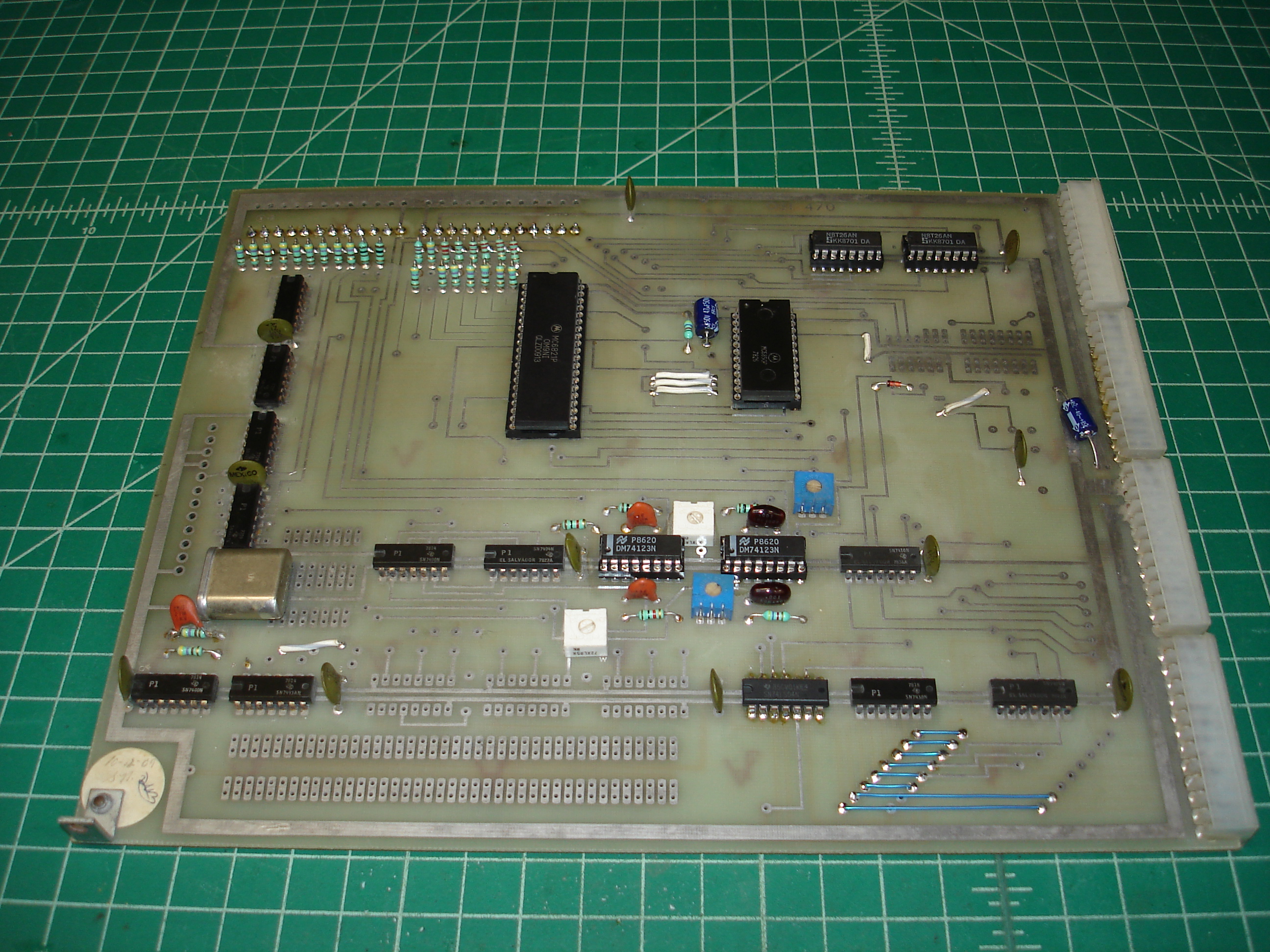
At this point, the board showed signs of life and was plugged into the C3-OEM system for further debugging…
A Backplane Fault and Other Weird Problems
This was the point at which the repair started to get weird. First of all, I decided to check out a memory test program posted to the osiweb.org forums by Mark Csele – you can find that program at the bottom of Mark’s OSI Software Tools page. It’s apparently a very intense memory test, and started showing errors on my GW-OSI-RAM1. I switched to one of the prototypes for the GW-OSI-RAM1, which passed the test for over 256 iterations. Concerned that there might be some design flaw in the GW-OSI-RAM1, I built up another, which also failed the test…but at nearly the same address! I switched back to the prototype RAM board and continued work.
Trying to use the repaired OSI 470 RAM board in the C3-OEM produced bizarre results. I started with trying to adjust the 74123 circuits’ trimpots using the OSI timing diagram, only to find that, while I had a pretty strong clock signal from my SA800 8” floppy drive, the data signal was pretty much nonexistent, even on the drive itself. After switching to the known-good OSI 470B board, I had exactly the same conditions! After checking read/write head resistance values against good drives typically used with my IMSAI, I tried the drive again and found that it now booted with the borrowed OSI 470B, but that using the repaired 470 would cause the same issues again.
At this point, I got frustrated with the repaired 470 board and went back to chasing RAM problems with the GW-OSI-RAM1. I eventually discovered that my C3-OEM had a backplane problem! Apparently years of flexing with insertion and removal of the high-insertion-force KK-156 connectors used on OSI boards had cracked a trace or solder joint. This seemed like a good reason to finally clean up some of the spare parts I have and build a test bench system.
Building a Second Challenger III
Many of the spare OSI boards I have, and indeed the borrowed OSI 470B that had been running in the C3-OEM, came from a previous employer’s Challenger III system. This particular system was never installed in a case, its owner simply mounted the backplane to a plank of wood and ran it with the cards standing up, with the backplane, power supplies, and CD-74 hard disk system living on a purpose built shelf above the main operator’s console in the computer closet. Since there was no proper case for the system, and since parts had been borrowed to get the C3-OEM system up and running, I’d never done anything with the backplane.
The backplane was of course filthy, having sat open on a shelf for decades. I have the power supplies originally used with this system, but the 5V supply is a truly massive Lambda linear supply (it must weigh at least 40 pounds, by itself), and since the backplane was going to be used on the test bench, I decided to just power it with my Lambda LPT-7202-FM triple voltage adjustable bench supply, which has current limiting. Here’s a shot of the entire test system, up and running:
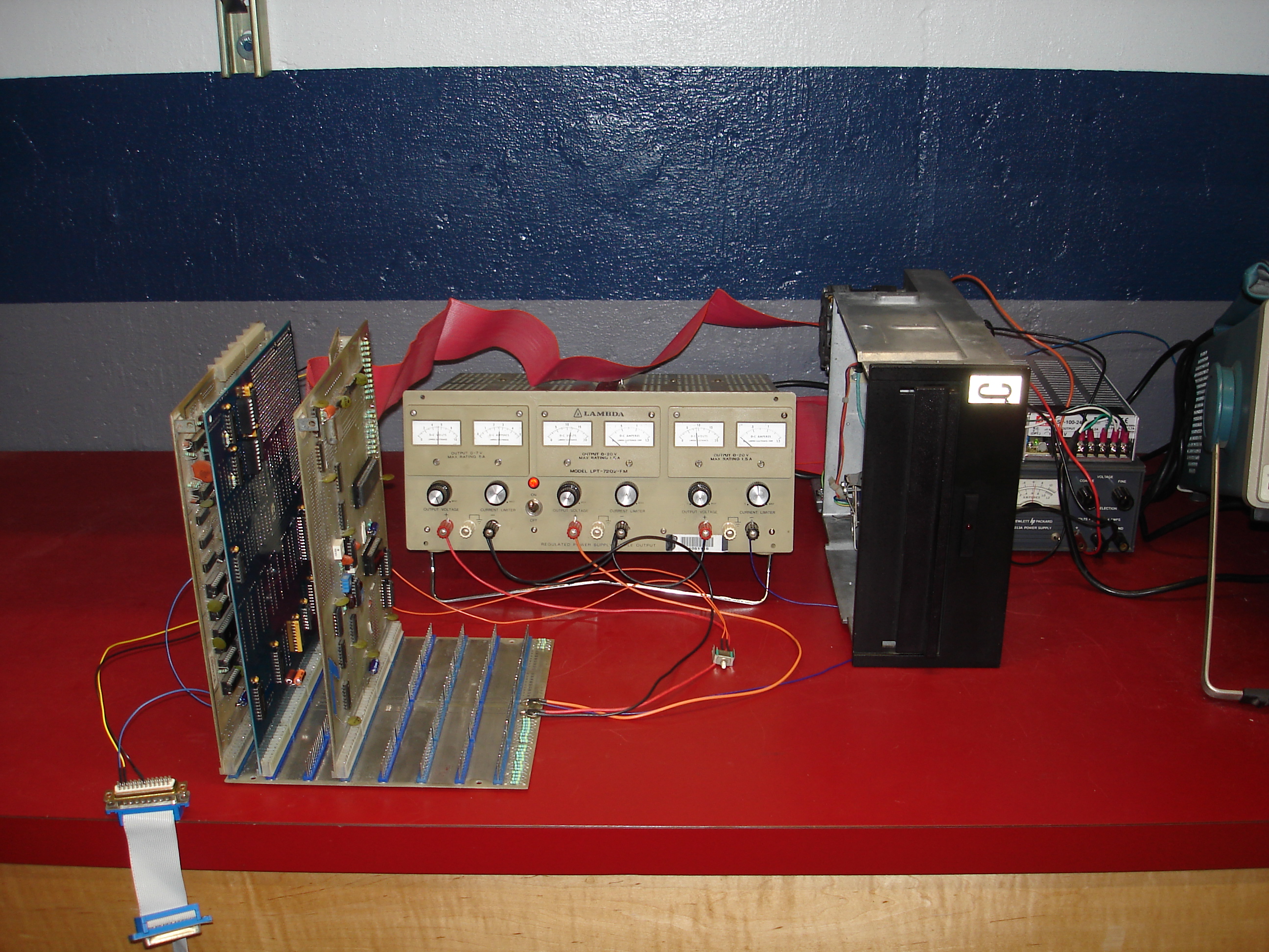
The backplane connects to the bench supply via flying leads: red for +5V, black for ground, purple for -9V, and orange for +12V. Using the bench supply allows for not only current limiting (helpful for boards with shorts), but also allows backplane current consumption to be monitored via front panel meters. The flying leads to the power supply were soldered to the backplane (a factory-cut-down OSI 580), and epoxied down for strain relief:

Here’s a shot of the backplane in the configuration I used for finishing the repair of the 470 board:
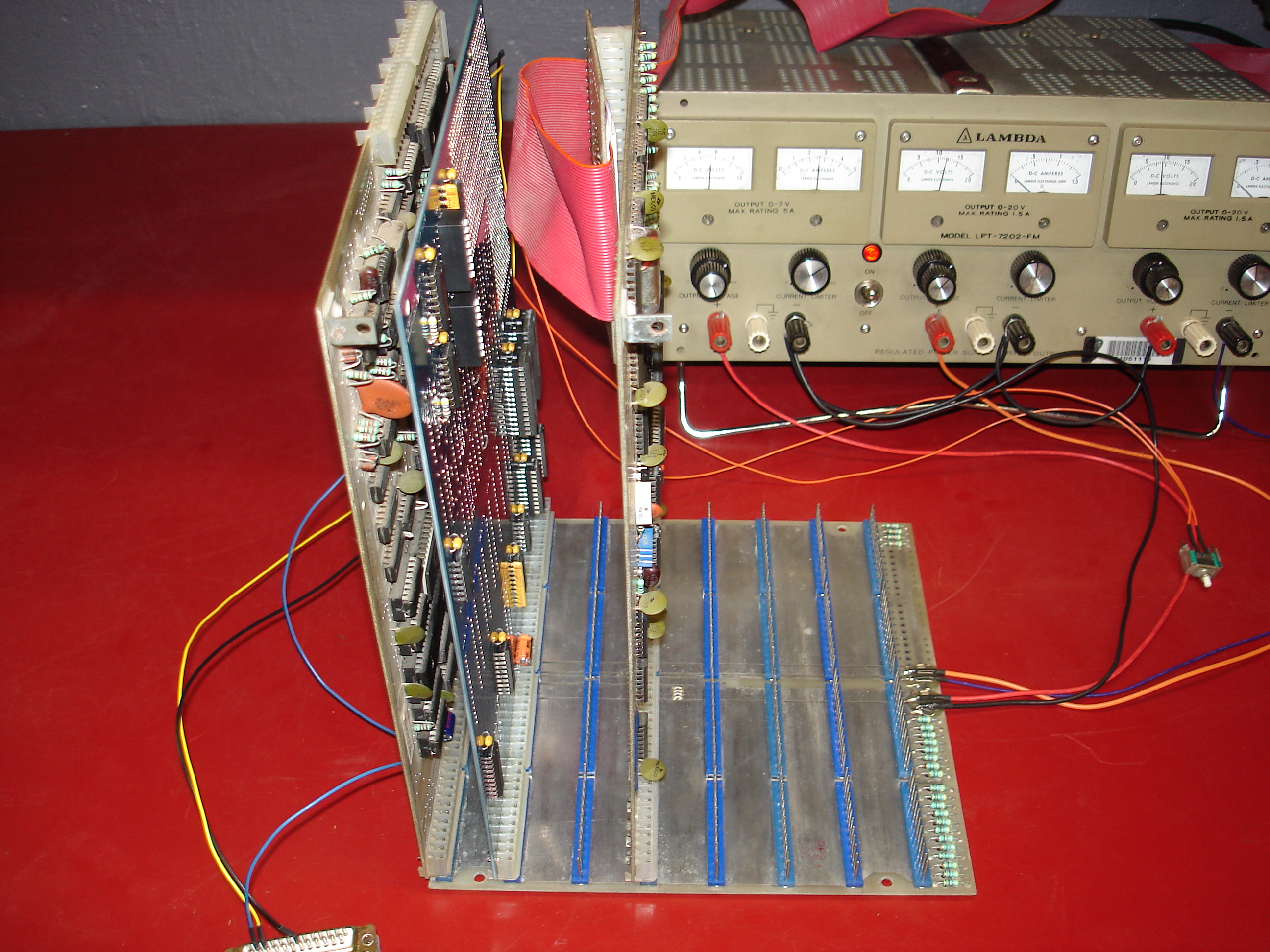
The board set consists of the OSI 510C triple-CPU board originally used with this system, a GW-OSI-RAM1 configured for 48K of main memory and 8K from 0xD000 through 0xEFFF, and the OSI 470 controller being repaired. You can just barely make out a shadow from this backplane’s previous life: the small red “stain” between the sixth and seventh card slots is a faint marking that reads, “COMP SIDE THIS -> DIR” – presumably in place so that no one would put a board in backwards.
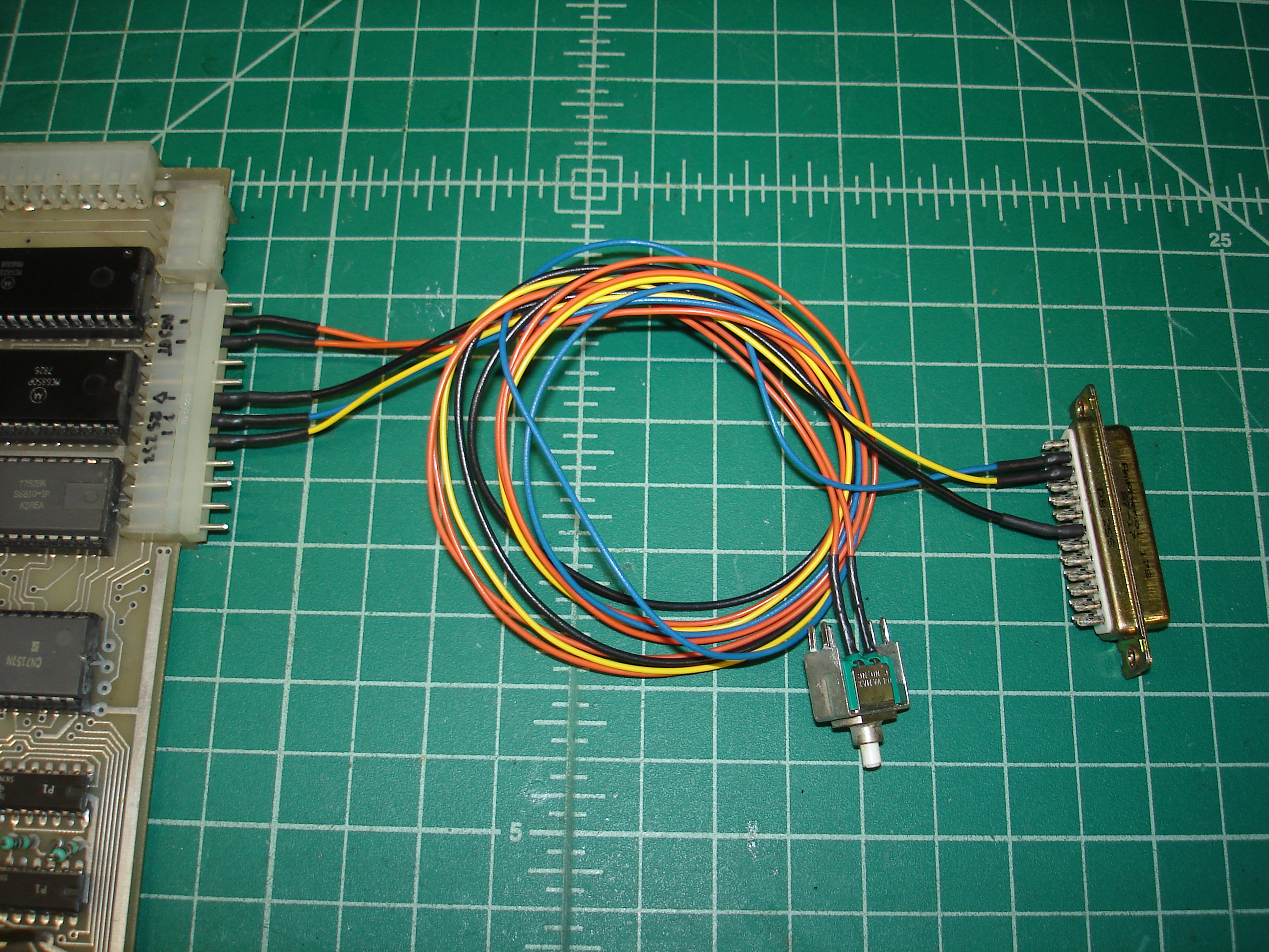
The OSI 510 rev C triple-CPU board was repaired some time ago in the C3-OEM system. It currently contains a UV EPROM with monitor/boot code, instead of its original mask programmed ROM, which is probably fine but was changed out during the 510 rev C’s repair. I made up a small breakout cable for the console port and reset switch:

To the right of the backplane is the Shugart SA800 and power supplies used for testing:
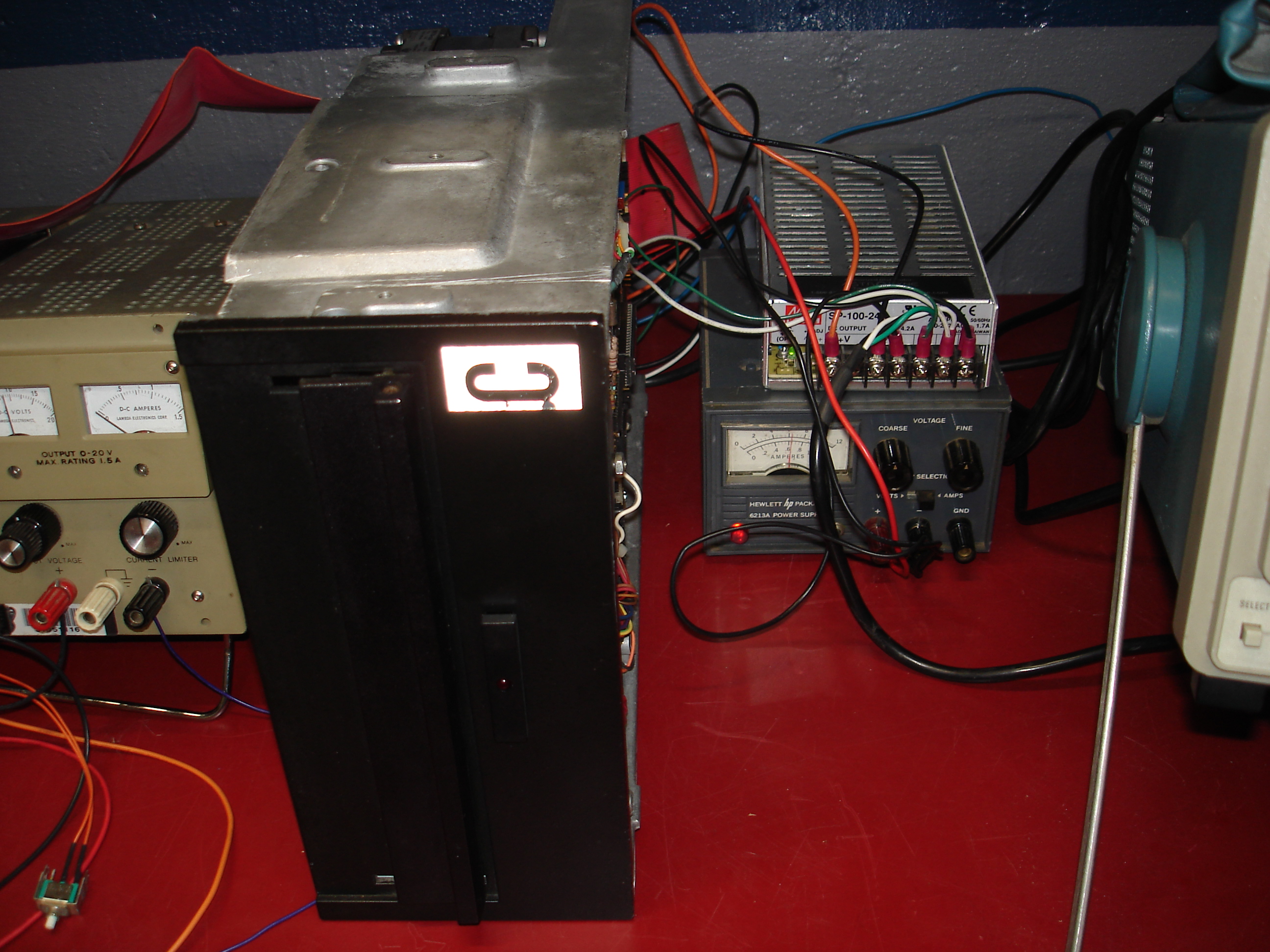
The SA800 is a single-sided 8” floppy drive which includes an onboard single-density data separator, which is necessary for use with standard OSI disk controllers. This particular model is one of the LSI revisions, which, handily, does not require a -5V supply. +24V DC is provided by the silver-cased Mean-Well switching module, the 120VAC spindle motor power is wired in parallel with the Mean-Well supply’s input connections. The small gray HP adjustable supply provides +5V to the floppy drive for logic power – this can be supplied from the OSI, but this is not the only system on which this SA800 is used.
Despite having a new system set up which passed memory test for many hours and booted with the known-good OSI 470B, I kept experiencing the same weird no-data problems with the repaired 470 board! I ended up trimming in the 74123 for the read circuit using a function generator. Still, the repaired 470 board failed to function and appeared as if it was not receiving data. I checked the OSI timing diagram against the known-good 470B board, both agreed.
By chance, I happened to notice that, after powering down and swapping to the known-good 470 board, the head positioning stepper in the floppy drive jerked when power was re-applied, as if the stepper was sitting between steps and in between two tracks on the floppy. I powered off and manually ran the head leadscrew to somewhere in the middle of its travel. With the good 470B board, the system was booted from the H/D/M? prompt…it moved to track 0, and started up! After swapping to the recently repaired 470 board and attempting to boot, then swapping in the known-good 470B, I once again had to manually move the leadscrew out and let the drive seek back to track 0.
The source of this problem turned out to be a defective Motorola 6821 PIA on the repaired 470 board! Apparently it was over-stepping the drive when booting, going past the track 0 position and probably hitting a mechanical limit. The track 0 sensor still saw the track 0 flag on the head assembly and the drive reported as being on track 0, the computer had no way to know that it wasn’t. Since the OSI floppy boot code is pretty minimal, it does not step the head forward and then back to track 0 when it initializes a drive (something that more modern machines do). Manually advancing the leadscrew results in head motion on boot, which takes care of the stepper being too far past track 0.
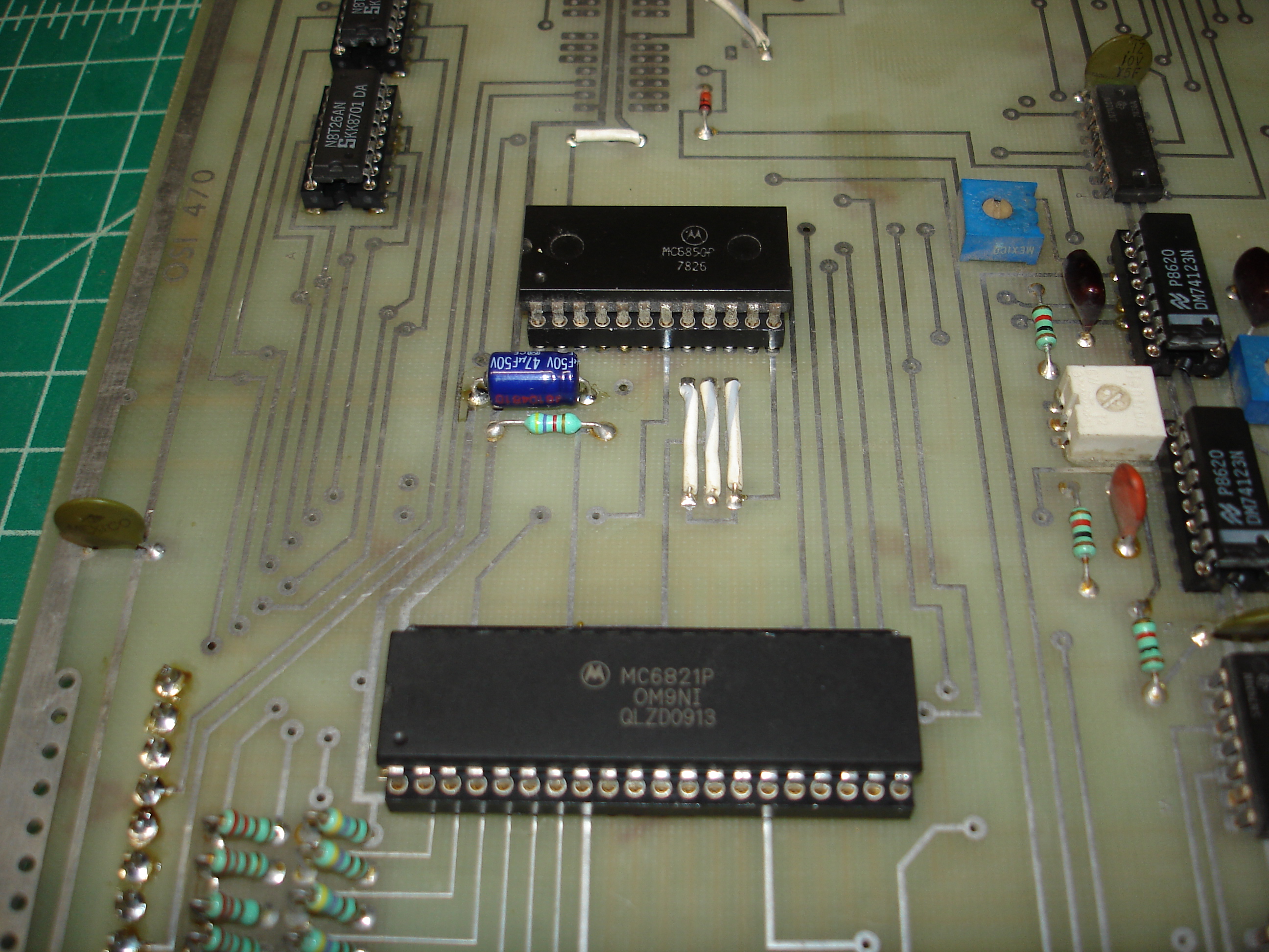
With the 6821 PIA replaced, the repaired 470 board was fully functional! The 74123 for the write circuit was reinstalled and a format/write test performed. I’m not sure what was wrong with the original 6821, it was basically functional, as the I/O ports could be read from and written to. Perhaps it had a noisy output on the *STEP line, resulting in double-stepping or a partial step or something.
yaks shaved