Topic: Making new OSI 560Z boards
Date: 2017 FEB 26
Quick Links
- OSI 560Z Manual, with Schematics
- OSI 560Z Software Listing
- osiweb.org Forum Build Thread
- 506Z Driver Package LOD File, courtesy Grant (Klyball)
Introduction
One of the well-known but unobtainable boards for the Ohio Scientific bus is the OSI 560Z “Processor Lab.” This board acts as a coprocessor board, interfacing a Z80 and/or an Intersil IM-6100 to the OSI bus. It contains a top-side bus that provides separate memory for the coprocessors, which is accessible through a 4K window from the OSI bus. It was intended for experimenting with other processors, running existing non-6502 code, and as a shared memory pathway between 6502-based systems.
The inclusion of the IM-6100 is a particularly interesting feature, as the IM-6100 implements DEC’s PDP-8/e instruction set. This means that PDP-8/e code can be run on a properly equipped Ohio Scientific system. Presumably the intention was to allow users to make use of the large quantity of software already available for the PDP-8, much of which was of a laboratory or scientific nature. While that’s still true, it also now provides a cheap way to experiment with the PDP-8 instruction set with actual hardware. It’s not a real PDP-8/e, but it’s not a software simulation either!
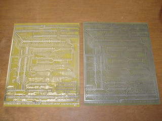
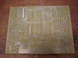
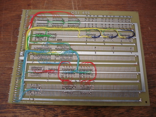
Until recently, the only OSI 560Z that either I or Dave Fenyes (maintainer of osiweb.org) knew of was owned by Bill Dromgoole. He has exhibited his Ohio Scientific system at previous VCF East events. That changed when a lot of blank Ohio Scientific boards showed up on a popular online auction site. It included a 560Z board! Thanks largely to other members of the community, I was able to purchase this lot of boards. As with the OSI 495 protoboard, I intended to have this board scanned at Mile High Test Services and then reproduced. That effort is now complete, and new reproduction OSI 560Z boards are available for anyone who wants to build one:
Reproducing this board spawned the “OSI Preservation Project,” a coordinated effort between myself, Dave Fenyes, and a few other members of the community to scan and preserve Ohio Scientific board artwork. The eventual goal is to offer new-production boards, parts kits, and assembled/tested boards to the community, reducing the scarceness of critical Ohio Scientific components and allowing more people to participate in the hobby.
While I was working on duplicating the board from an original, Grant (KlyBall), another OSI hacker who had reproduced several Ohio Scientific boards, was also working on a reproduction. His board was made from schematics and a fresh layout that mimiced the look and placement of the original board. He got his board in before my small batch arrived, and started a thread on the osiweb.org forums, which you can read here. He also prepared a .LOD formatted file with the driver software, which is critical in bringing up and testing the 560Z. His .LOD image can be used with a serial based OSI system with no disk drives.
Test Setup
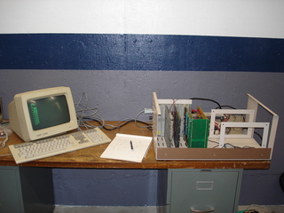
My system for building and testing the 560Z board consisted of my Challenger 3 chassis with the following boards:
- OSI 510 triple CPU board, serial console, 65A ROM monitor
- OSI 524 RAM board, populated with 48K of 6116 static RAM
- Reproduction OSI 582 4-slot backplane, two slots populated, with pull-up resistors on
/NMIand/IRQ - Custom 32KW 12-bit RAM board based on my 32K prototype
- 12-bit lamp register, added to the 32KW RAM board
Additionally, a serial terminal or computer with RS-232 port and terminal emulator software are required. A computer with terminal emulator is recommended as it makes loading the 560Z driver package easy. I used a laptop running Slackware Linux 14.2 and the minicom terminal emulator and communications package. To load the driver, boot into the OSI 65A ROM monitor (answer M at the H/D/M? prompt), set the terminal with a 5 mS per-character pacing delay, and paste in the LOD file (CTRL+A, Y in minicom). Sending the file in plain ASCII mode did not work for me. Here’s a picture of the setup, on one of the workbenches in the shop:
Building the Reproduction Board
Armed with the OSI 560Z Manual, I started assembling and testing one of my reproduction boards. The 560Z uses a few unusual and hard-to-get components. Since I’ll be offering a full parts kit, I inquired about the unusual bits with my components suppliers. The following were harder to obtain and were purchased in sufficient quantities to offer kits:
- 74LS365, direct substitute for 8T95
- 8T26 quad inverting bus buffer
- 74LS125 quad tristate buffer
- Motorola MC6821, direct substitute for MC6820 (OSI even made this substitution)
The rest of the TTL is relatively common and easy to obtain. I had enough in my parts bins to build up one of the boards.
Of course, to run PDP-8 code, you will also need an Intersil (or Harris) IM-6100. In months of searching I have yet to find a components supplier with any of these available. Fortunately, I had acquired a few over the years, and Dave agreed to make several available for people who had preordered parts kits. Several other hobbyists had acquired IM-6100s in the past, some specifically in case they ever found an OSI 560Z board!
Ohio Scientific recommended building up the board in stages, since it’s fairly complex and presents opportunity to damage expensive components if it’s misconfigured. The manual recommends starting with the Motorola 6820 PIAs first, and checking their functionality before adding anything else. I followed their instructions and tested the 6820s using the 65A ROM monitor with my Challenger 3. The board was addressed for the standard 0xE000 starting address, which puts the PIAs in a 256-byte block starting at 0xF000. Set up the data direction registers and poke a few bytes through the PIAs as outputs, and read in a few pins as inputs.
The next block to build is the 4K “porthole.” This is the circuitry that maps 4K of the SYS bus onto the MOS side for editing and transfers between the 6502 and the 560Z’s memories. I found a few omissions with the manual here:
- Install 74LS75 at IC N and 8T26 at IC O if you want 12-bit porthole
- Install 8T95 at IC CC if you want the porthole to be able to write
Note that, strictly speaking, the 12-bit function isn’t really the “porthole” – the high 12 bits come from a PIA port, so you can’t directly modify 12-bit words through the porthole. I found it more convenient to add the 12-bit capability at this point though, since I was testing through the 560Z driver package.
With the PIAs and porthole thoroughly tested, it’s time to add in the coprocessors. I started with the Z80, since it seemed the least challenging to talk to. After a false start, I discovered that I had a dead Z80! Once it was replaced, the test code in the 560Z manual executed correctly. I also tried a few small hand-written test routines to further verify operation.
Testing the IM-6100 capability was a little more challenging, partly because all of my IM-6100s were of unknown electrical condition, and all but one was in very poor physical condition. They had been stored in black antistatic foam. Some types of this foam break down with age and become corrosive. Of the five IM-6100s I had, several had to be soldered into machine pin sockets with patches made to fix rotted-off pins. With one IC I had to grind back a bit of the plastic body to expose some of the lead frame, as one pin had broken off completely flush with the body!
In any case, two of the IM-6100s were functional, while three were dead. One came with a sticker attached with a question mark, so it’s not surprising that it was non-functional. Hopefully this sample isn’t representative of average IM-6100 survival rate!
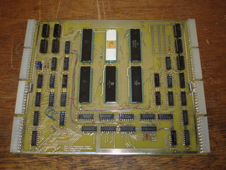
Here’s the finished 560Z board, with a Z80 and IM-6100 installed:
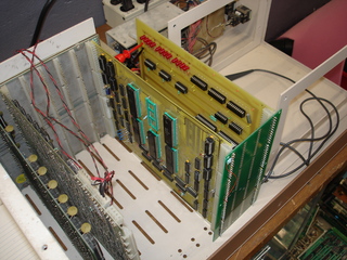
When installed in a regular OSI system, the 560Z goes in “backwards.” Not sure what the idea was with this design, but on assembling the board I was convinced that something had gone wrong with the scanning process and I was now the proud owner of a batch of useless boards! It’s convenient to install the 560Z in the frontmost slot in the chassis, which allows the short backplane to overhang empty space. I moved the rest of the OSI boards back further so that I could access the front of the 560Z with my logic probe for testing and debugging. Here’s a picture with the 560Z hooked to a custom 32KW RAM board with the reproduction 582 backplane:
MOS vs SYS Bus
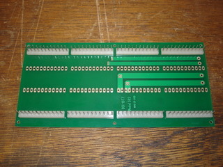
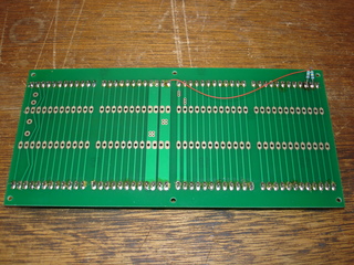
With the 560Z board, “MOS Bus” refers to the bus connectors that get you to the controlling system – usually a 6502 based OSI. The “SYS Bus” is the bus at the top of the 560Z board which connects to the memory and devices to be used by the coprocessors and/or accessed through the 4K porthole. Unless you add memory directly to the 560Z board, you will at least need a RAM board on the SYS side of the bus. To achieve this, a small backplane is required. The 560Z manual recommends getting a regular terminated OSI backplane and “shear, nibble, or saw off a portion” to use with the 560Z’s SYS bus. Instead, I used a reproduction 4-slot OSI 582 backplane, purchased from Grant (Klyball) for use in bench testing boards. You’ll need to add two pull-up resistors to the /NMI and /IRQ lines (bus pins 2 and 3):
Memory
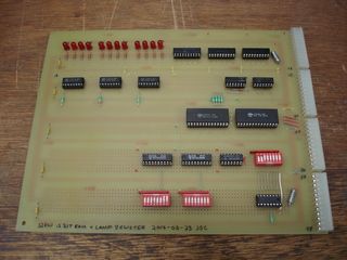
If you’re only interested in using the porthole feature or the Z80 (or other 8-bit processors), then any OSI 8-bit RAM board will work on the SYS bus. If you want to use the IM-6100, you’ll need a 12-bit RAM board. The only Ohio Scientific RAM board that supports a full 12-bit data bus is the OSI 420, an early board using 2102 static RAMs. In addition to being hard to find, 2102s draw considerable current and will probably add to reliability concerns with the system. To get around this, I built a 32KW 12-bit RAM board based on my 32K prototype. The RAM section is essentially the same as with the 32K board, but includes an extra SRAM and data buffer for the extra four bits:
I included a 12-bit lamp register on the 32KW RAM board. A lamp register is simply a memory location that, when written to, displays the bit pattern on LEDs. I grouped the LEDs in fours, which is appropriate for hexadecimal but somewhat unintuitive for octal. This is very handy for simple status display, which aids in debugging and testing.
The lamp register was used in my check-out of both the Z80 and IM-6100. I recorded a video of the IM-6100 controlling it. The 560Z driver is running the IM-6100 in slow clock mode (R0100 from the driver interface):
If you’re interested in purchasing a reproduction 560Z board, parts kit, or assembled/tested unit, please use the contact form.
PDP-8s simulated
