Topic: Testing and repair of a CD-23, part 1
Date: 2023 JUL 26
I’ve had this Ohio Scientific CD-23 disk subsystem for a while. It belonged to Burgess Macneal before that, and Burgess recalls it having come from George Massenburg. Some time earlier in 2023, some of the mid-Atlantic OSI hackers started talking about doing an OSI specific workshop at one of the museums in the area and focusing on trying to get my CD-23 running, in hopes of pulling data off. In particular, Crawford Griffith has larger plans for recreating a modern workalike to the OSI hard disk package, using a solid state data store.
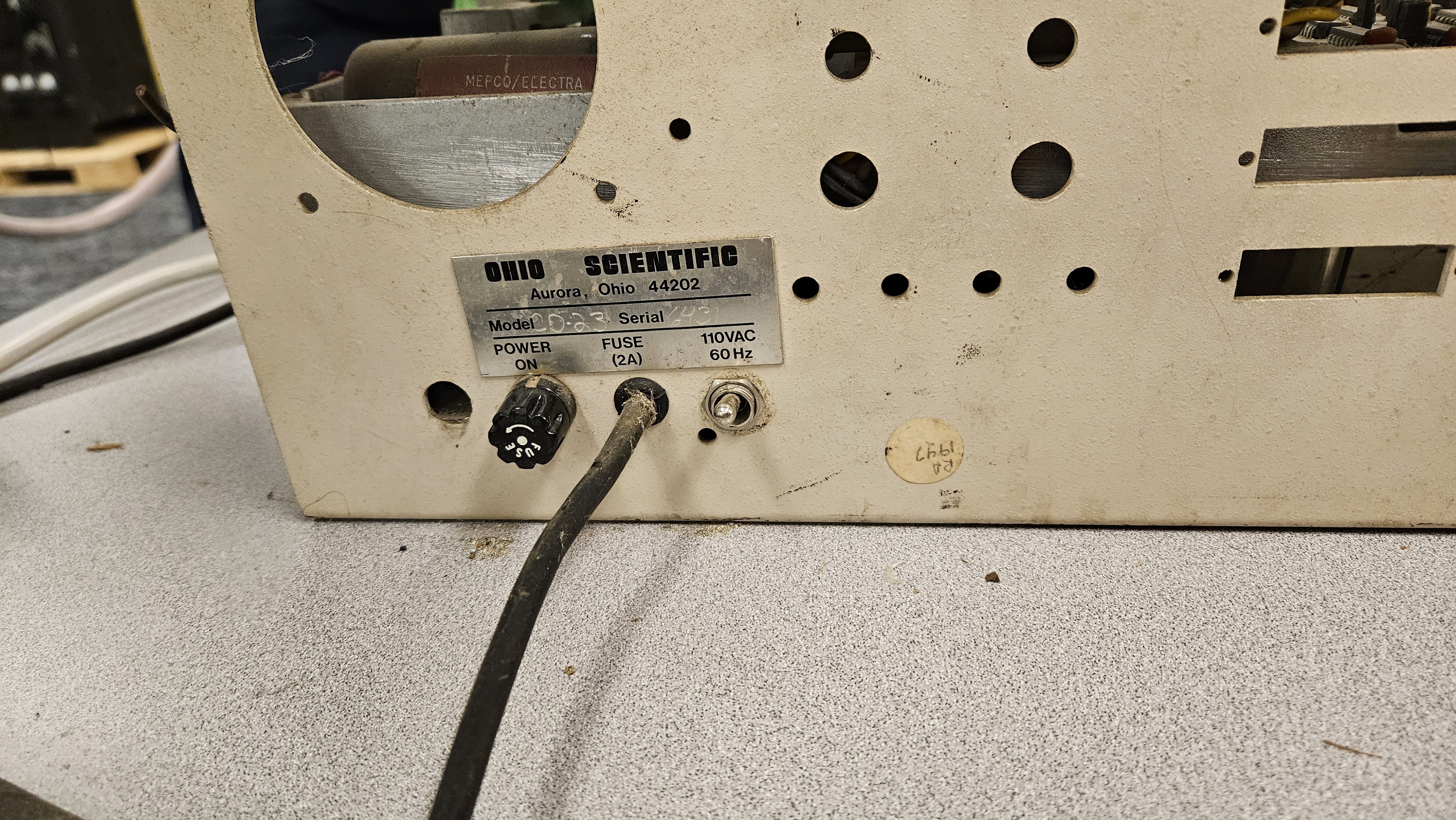
I’d initially thought Burgess had given me a CD-74 system, but on closer inspection, it’s really a CD-23:
We finally got together and hacked on the CD-23 at the July 22 - 23 Swapfest and Repair Workshop at System Source Computer Museum in Hunt Valley, MD. The geographical location was sort of interesting, as Burgess had run Sontec at a location in Cockeysville, MD before moving operations to Virginia! System Source has a large space available for hobbyist workshops, so after the outdoor swapfest, we moved the CD-23 and related items inside and started hacking.
Cleaning
The first task was cleaning:
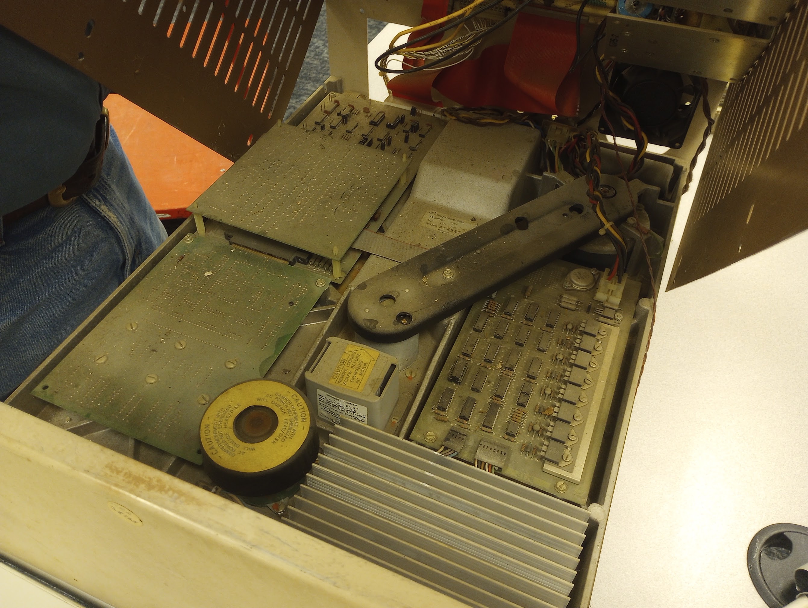
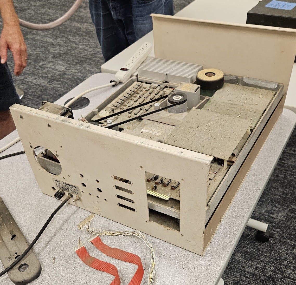
This was the first look in the chassis for everyone at the workshop. Sark had helped me retrieve this system from the ITI Audio/Sontec building in Ripplemead, VA probably in 2013, and we’d opened it at that point to put a screw in the spindle lock. It was also checked for exact model number before the workshop, but otherwise left untouched. Here’s some more pictures of the initial condition:
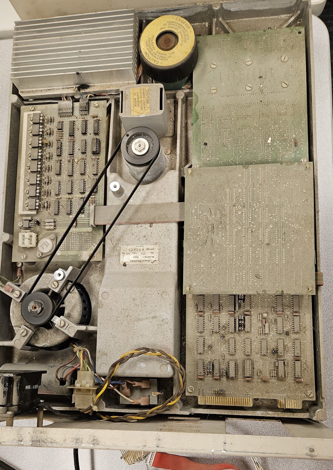
The bottom of the CD-23 chassis houses a Shugart SA-4008 drive, which is a Winchester technology hard disk capable of storing around 29 MB unformatted, or 23 MB formatted (hence the CD-23 designation). The HDA and platters are on the underside of the drive, with the electronics and spindle drive on the top. Spindle drive is provided by a 1/12 HP AC motor belted to the spindle shaft!
There was probably 30-40 years of accumulation of dust, dirt, and a little bit of mouse mess in this drive. Burgess had never removed his Challenger 3 system from the area in which it was run after it was replaced by PC clones in the 1980s, it was simply shut off. The CD-23 had nothing sitting on top of it to avoid restricting airflow, so it was fairly open to dirt ingress. There was also a roof leak near the OSI area at some point, though it does not look like the CD-23 took a direct leak.
Anyway, cleaning began with removal of the top cover (to which the power supplies and interface board mount), and brushing out dust, dirt, and chunks with a brush while vacuuming:
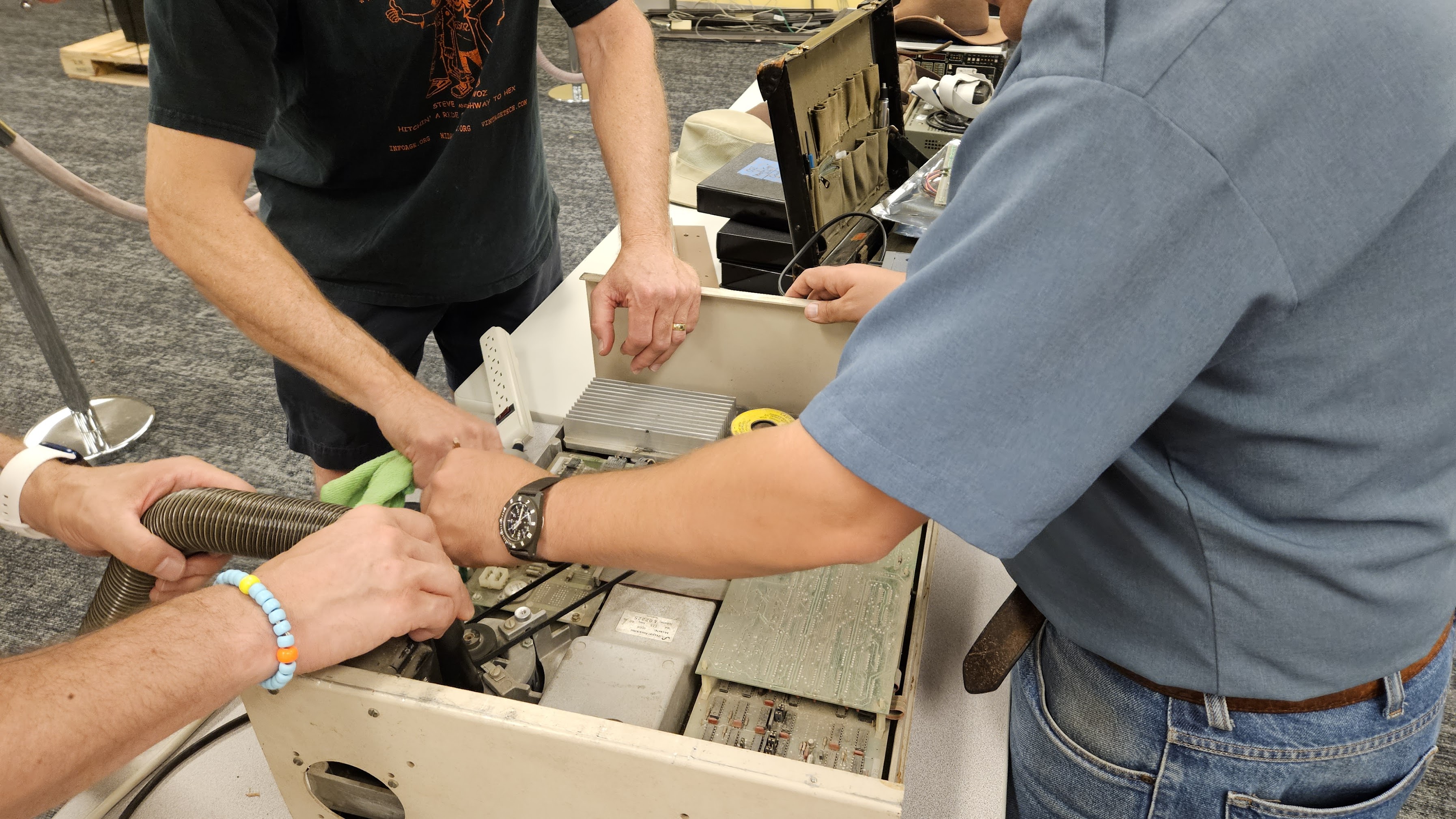
The enclosure was also wiped down with glass cleaner and rags.
Mechanical Testing
After cleaning, we unlocked the spindle and prepared for initial power-up. Both the spindle and AC motor were free and rotated easily, and the belt was still pliable and in good shape! AC wiring to the power supplies mounted in the cover was cut: the only power provided was to the SA-4008 spindle motor and a small cooling fan. We made sure to record the first spin-up:
It worked! Sort of, anyway. At the end of the above video clip, the spindle drive motor shuts off abruptly and the drive coasts to a stop. It would not spin up after a reapplication of power. The motor frame was pretty hot to the touch, though, so we suspected a thermal protection switch had opened. The motor start capacitor was checked using a Simpson 260 and found to be in at least acceptable condition. After cooling for a while, we were able to start the spindle drive motor with the belt removed. It still shut down after running for a bit, so we pulled the drive motor:
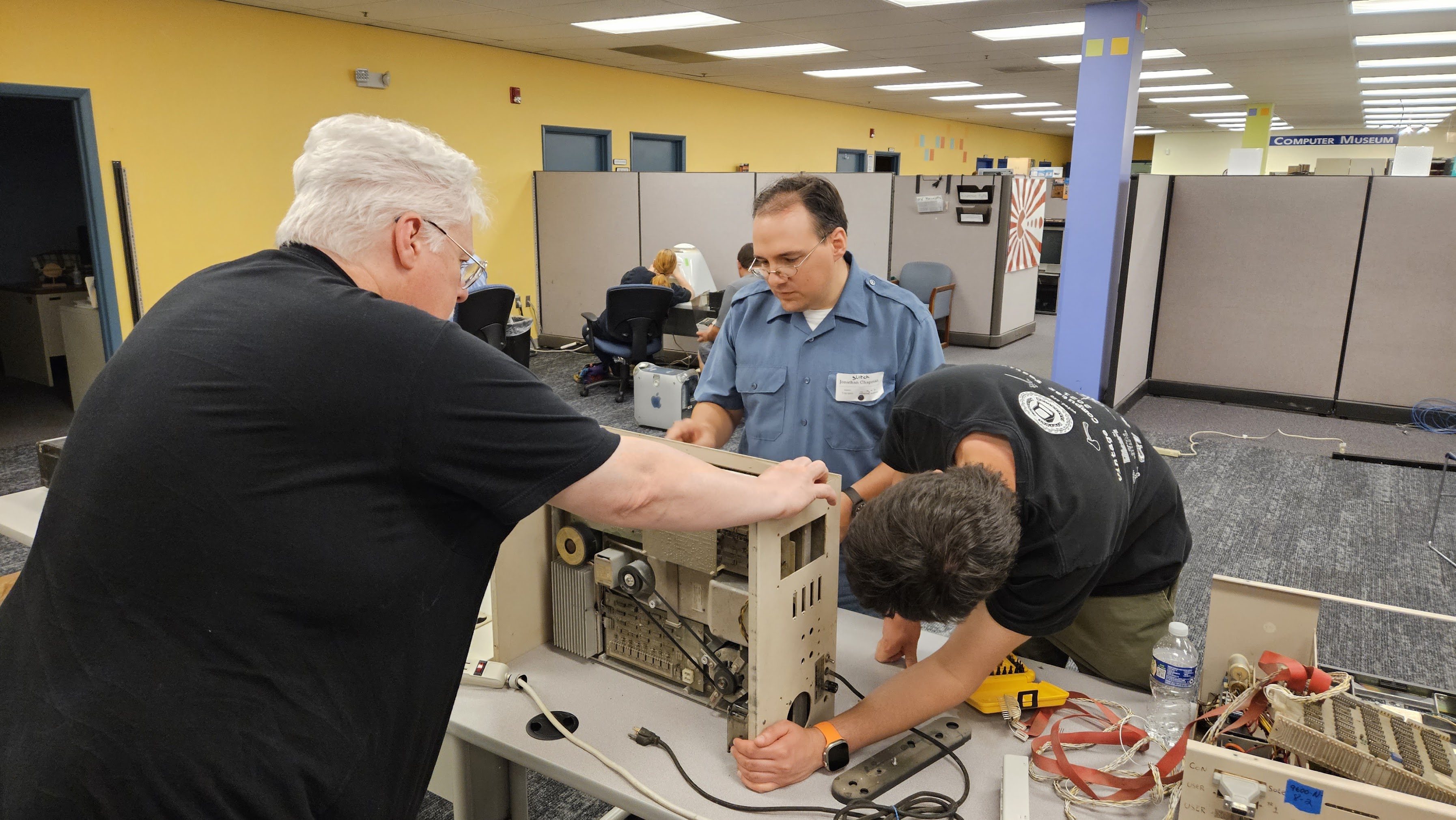
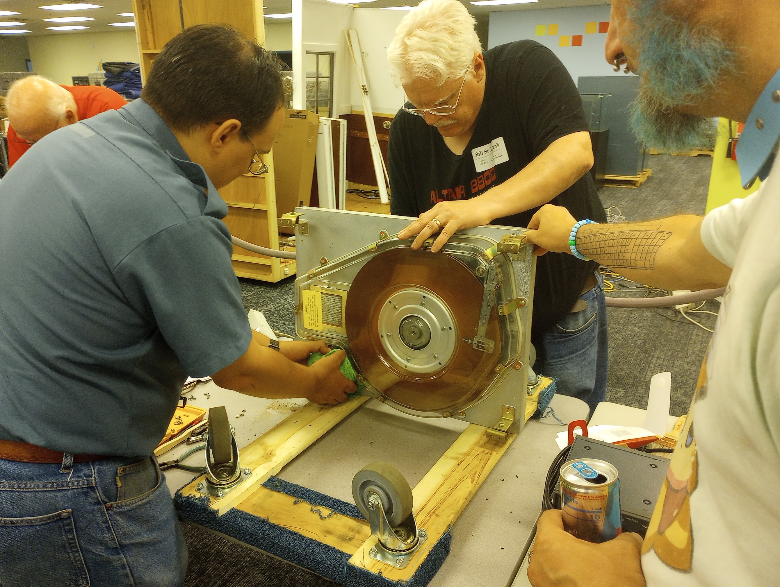
This required removing the SA-4008 from the CD-23 enclosure as the motor drops out the bottom, and the mounting bosses are part of the drive casting. Bill Sudbrink and Mouse helped with this process. The nuts which hold it to the bottom are not captive, they’re just regular hex nuts and an internal tooth lock washer, so removing the drive required removing the bottom side rails of the enclosure. Fortunately, that wasn’t too hard on this enclosure – some of them have Loctite, Pliobond, or some other thread locking goop applied and can be really difficult to remove. Here’s a look at the motor’s data plate:
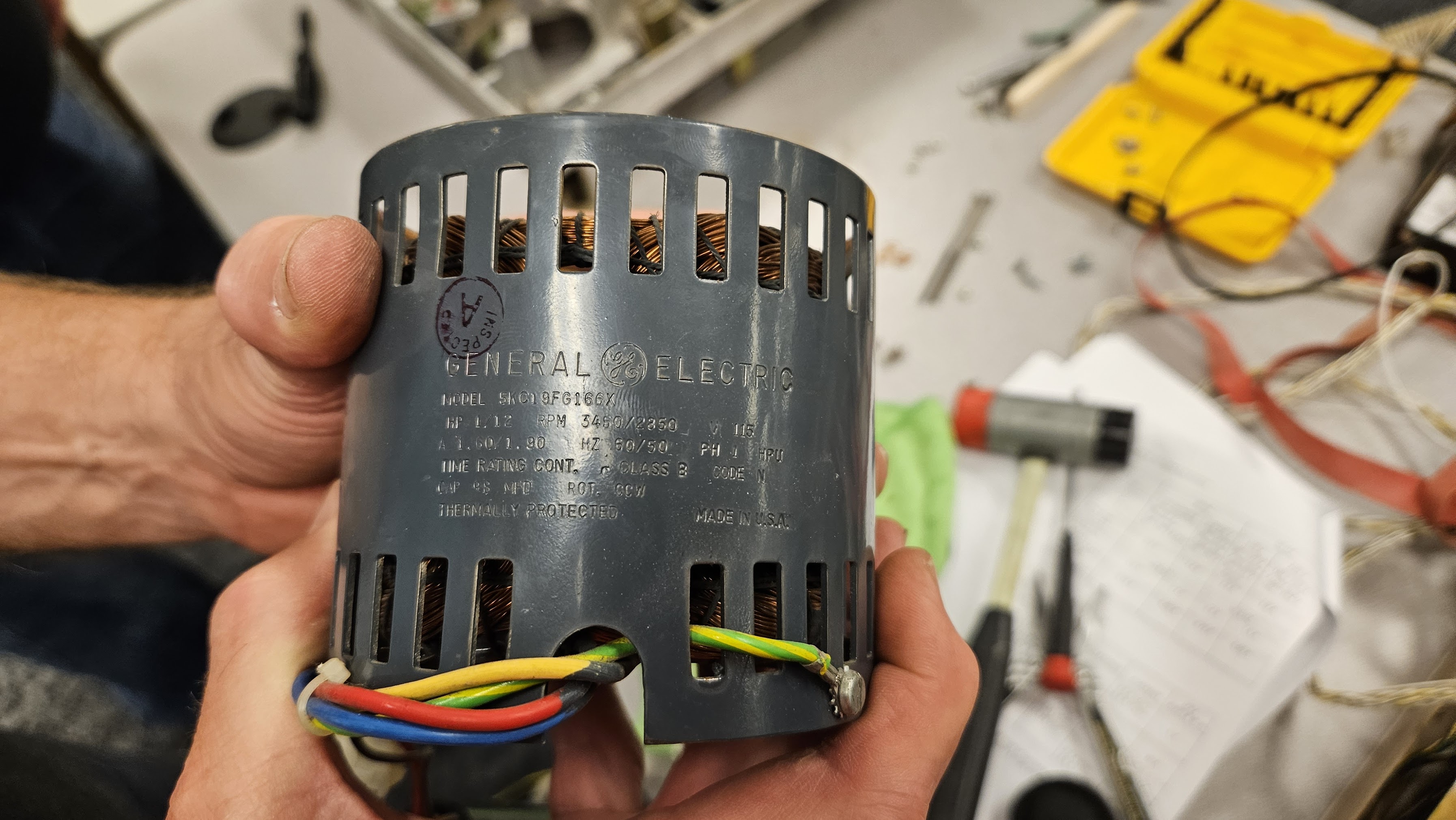
It’s a General Electric 5KC19FG166X:
- 1/12 horsepower, CCW rotation
- 115 V AC, single phase
- 3450 RPM, 1.6A at 60 Hz
- 2850 RPM, 1.9A at 50 Hz
Bill Sudbrink noticed that not much air seemed to be moving through the motor and wondered if it was plugged up with dust or a mouse nest or something. The motor had some build-up in it, but not enough to overheat it. None of the windings showed signs of overheating, so we lubricated the bearings, closed it up, and reinstalled it. Our attention turned to the start relay:
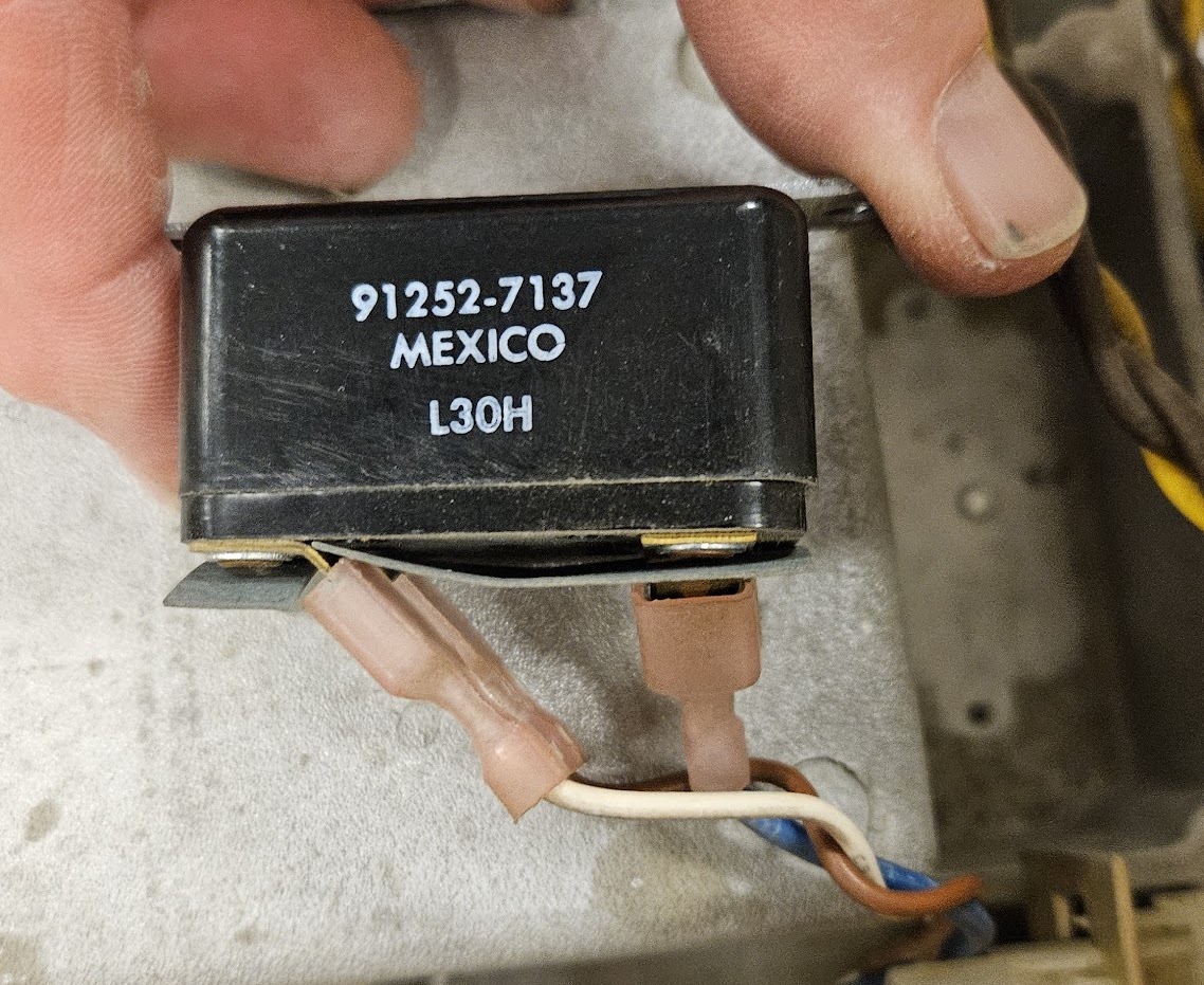
Bill Dromgoole was able to find a datasheet for the start relay. It closes and applies power to the start capacitor and winding when current draw through the run winding is above 5A. After the motor comes up to speed, the start relay drops out. This happens when the run winding current falls to around 3A. We decided to try manually starting it. Bill Dromgoole attached an alligator clip jumper wire between the start terminal and the capacitor. After applying AC power and letting the motor spin up, Bill yanked the jumper off. The motor ran quieter, and did not shut down after five minutes of run time, so we decided the start relay must be bad!
Powering Up the Electronics
The CD-23 uses two of the small Ohio Scientific modular power supplies and a modular 24V supply for stepper power. The OSI supplies always require recapping, and are not great supplies to start with, as they’re all the same supply: the 5V supply is just a 12V supply that makes a lot more heat! All three were in unknown condition, so we decided to run the SA-4008 and OSI 594 board from bench supplies. Fortunately, the DC connector on the SA-4008 is the same connector and pinout as those used on 8” Shugart floppy drives, so I already had a test harness made up.
+5V power was applied from a single-rail Lambda bench supply. Current consumption was checked and didn’t seem to be too high. This SA-4008 is jumpered for unregulated negative power: it regulates to -5V using a 7905 onboard. That rail was provided with a small HP bench supply, and again checked for current consumption. The 7905 output was also checked. Finally, 24V stepper power was applied. This was provided from a modular switching supply which has overcurrent protection.
The drive cabinet interface also requires +5V power:
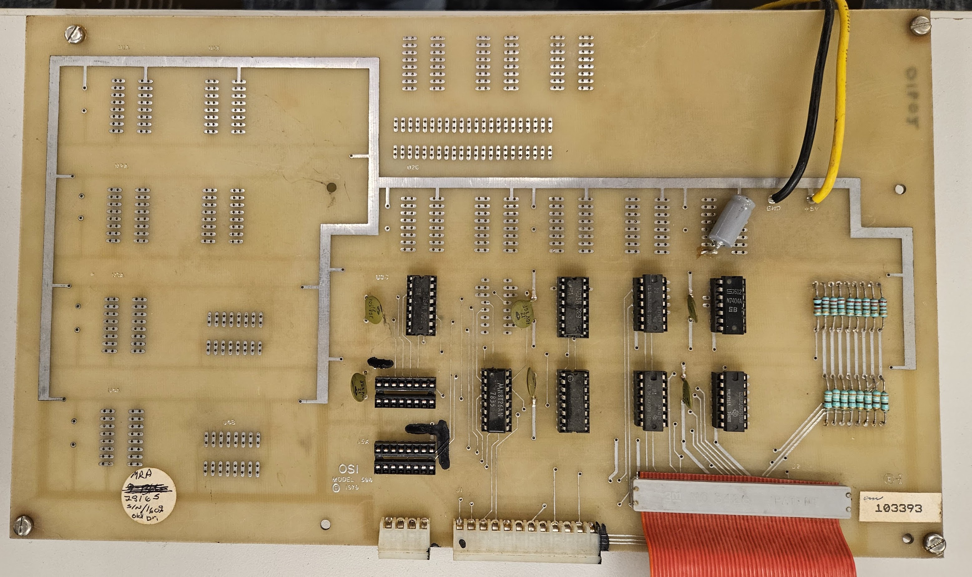
This board normalizes the interface of the SA-4000 series drives to what the OSI 590 controller expects to see. Ohio Scientific offered several drive options from several manufacturers in their various disk system combinations, and using a board in the drive cabinet was how they accounted for differences.
Nothing smoked or got hot, and power consumption looked OK, so we moved on to testing!
Testing the Setup
Dave Gesswein had brought his MFM widget to the workshop, in hopes that the drive interface would be close enough to SA-1000 for him to dump it directly. Unfortunately, the SA-4000 series outputs separated clock and data, which Dave’s widget does not currently handle. We were forced to use the Ohio Scientific to interact with the CD-23 system. For the test setup, I brought:
- Lambda LPT-7202-FM triple-voltage power supply
- Burgess’s OSI 580 backplane
- Burgess’s OSI 510C CPU board
- One of my universal RAM boards
- Burgess’s OSI 590 disk controller
- Burgess’s OSI 525 dual port RAM board
Everything except the OSI 590 had been up and running in my shop before heading to System Source. This was basically how Burgess ran the CD-23 setup when he was using it, except he’d have been using OSI 520 RAM boards for main memory, and there was an OSI 470 disk controller and CA-10 multiport serial board in his system.
Crawford Griffith brought his C3-OEM system as a standby, in case we had any issues with my board set. It can be seen here next to the CD-23:
Bill Dromgoole also brought some spare OSI 590 and 525 boards, as well as the little two-slot “over the top” backplanes needed to join them together.
Before testing, I physically cut the trace to the write gate near the edge connector on the SA-4008. This would prevent any runaway program from causing an errant write to the disk, destroying data in the process. With the CD-23 cabled to the OSI 590 controller, it was time to power everything up together and try to boot:
You can see the flash from Bill Dromgoole pulling the jumper to the start capacitor! We were able to successfully check for the *READY signal on the SA-4008, and confirmed it was making its way to the OSI 594 interface. The *READY line goes low after the SA-4008 has spun up and stabilized, which takes approximately a minute and a half!
Stepper and Index Problems
We were unable to get either the OSI boot ROM or the experimental C3DUMP Mark Spankus sent to Crawford Griffith to move the heads. There didn’t seem to be holding power to the stepper motor, it turned freely with the disk spun up. Turns out that Shugart did not link the grounds for the DC rails at the connector! The grounds were jumpered at the bench supplies, and stepper power was restored.
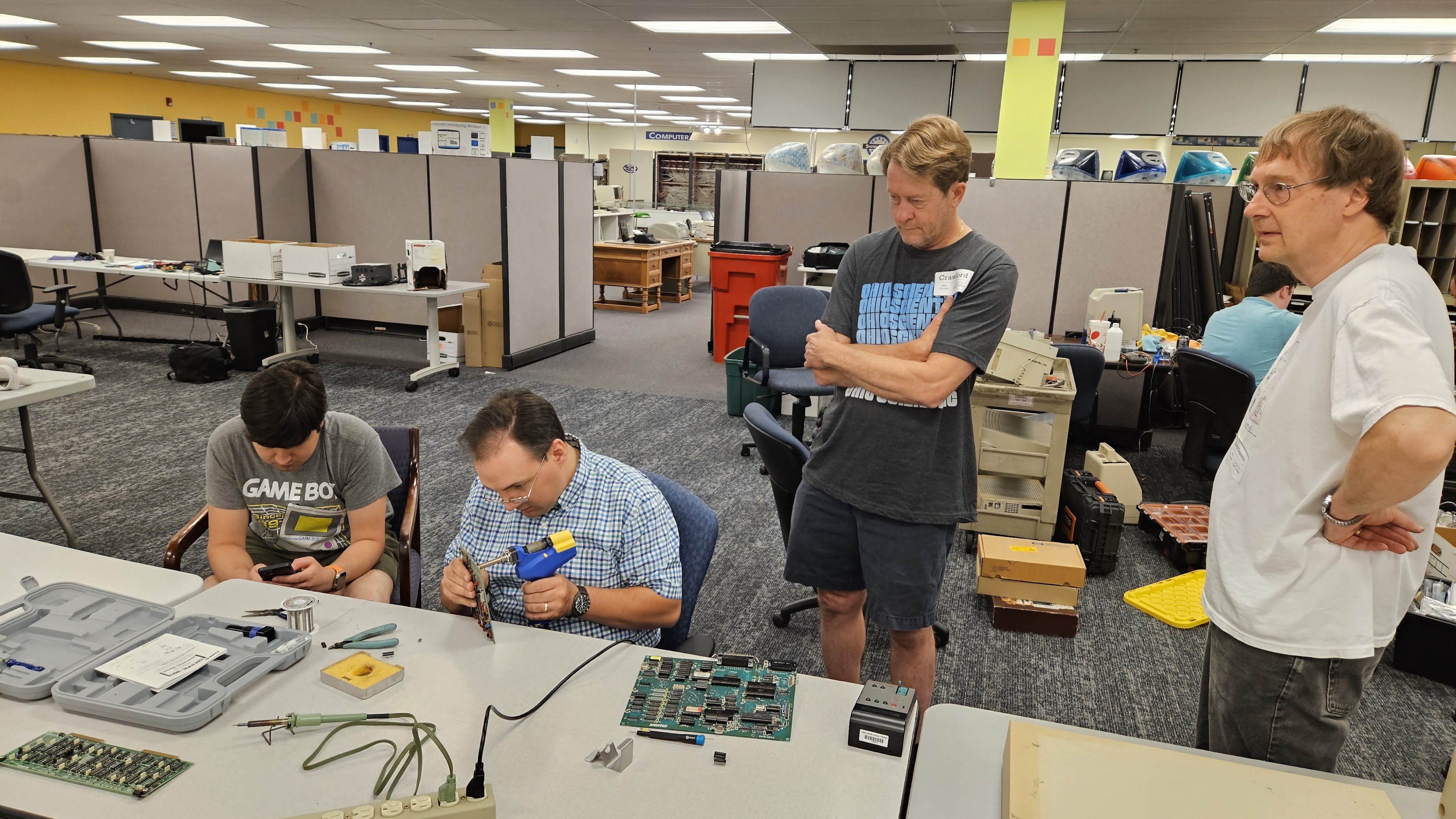
The next problem revealed itself by C3DUMP hanging indefinitely when trying to do operations on the CD-23. This turned out to be a missing index pulse, which was traced to a dead CD40103 counter. We’d given up hope on finding a replacement during the workshop, but Dave Gesswein was able to dig some up at his shop and brought the following day:
C3DUMP now progressed past the previous hang-up, but was not reading valid data. It would mostly read 0x00 with an occasional blast of 0x01. It did, however, step the heads in as it moved through the disk, which was progress. The system still didn’t boot, and the symptoms on trying to boot seemed to indicate the boot ROM was not finding track 0 correctly:
On to the next problem…
Read Data and Potential OSI 590 Issues
My initial thought on the C3DUMP output was that we weren’t getting read data from the SA-4008. Probing the edge connector, there was in fact no read data; moreover, the read gate was never being activated. If the read gate was grounded with a clip lead, we did get something that looked like it might be data, as well as clock pulses. At this point, we were able to confirm that index pulse and byte clock timing were in spec:
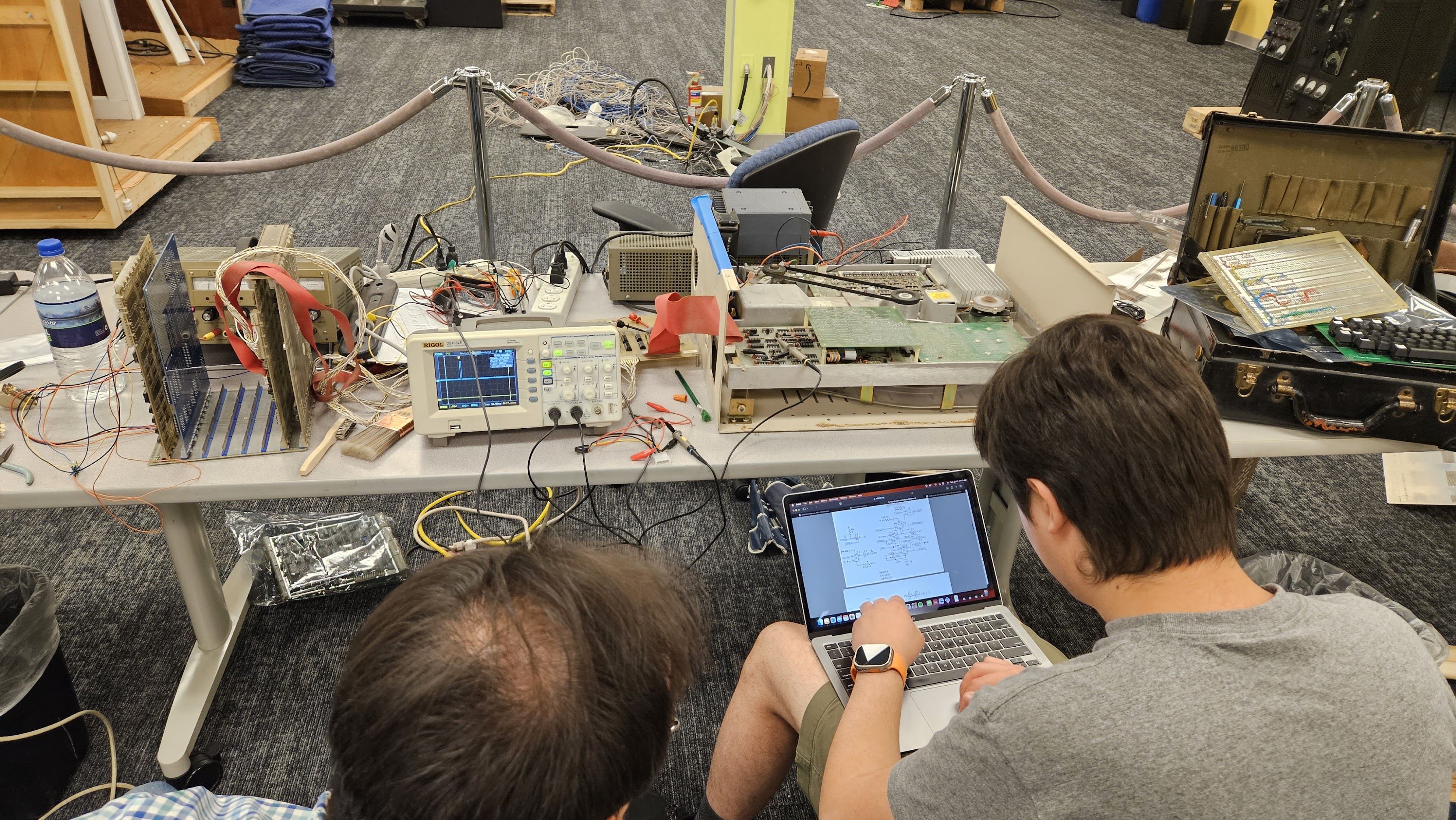
The lack of read gate activation points to an issue in the OSI 590 interface, rather than a SA-4008 problem, or an error in the experimental C3DUMP program. This signal is generated internally when a disk read is kicked off, and is not directly controlled by software.
Wrap-Up
At this point, everyone had to start getting ready to head home from the workshop. We’d accomplished the following:
- Cleaned and mechanically tested the CD-23 cabinet and SA-4008
- Found a faulty motor start relay
- Electrically tested the SA-4008
- Learned that DC grounds are not linked on the SA-4008
- Isolated an index generation fault on the SA-4008
- Confirmed the index timing was in spec
- Observed what was likely data on the first data track
- Isolated the read gate fault to the OSI 590 board
More cleaning will be done back at my shop, the OSI 590, interface cables, and some of the SA-4008 boards can be washed and dried. The motor start relay will be replaced so that the SA-4008 doesn’t have to be “jump started” every time.
Finally, I’d like to thank everyone who helped with the workshop weekend again. The CD-23 might be my drive, but the repair efforts have been entirely a community effort! All of the pictures and videos in this writeup were taken by Bill Dromgoole and Crawford Griffith.
giant Winchester drives repaired