Topic: Making a crystal/battery replacement module for the 48T02
Date: 2017 AUG 01
Quick Links
Introduction
Anyone with older Sun systems knows about dead batteries in 48T02 or 48T08 RTC/NVRAM modules. With a dead battery, not only do you lose your timekeeping functionality, but the system comes up with no Host ID or Ethernet address, diag-swtich?=true, and usually defaults to trying to boot from the onboard Ethernet interface. Since diag-switch?=true is set, the system will run long hardware diagnostics at power-on, greatly extending the boot time of the machine. Additionally, some Sun systems won’t boot at all with an invalid Host ID.
ST still produces a device with the part number of 48T02 in varying speeds, carried by the usual component suppliers. Unfortunately, these new units are both relatively expensive (around $13 USD apiece, plus shipping, last time I purchased QTY 1 from Mouser) and not entirely compatible with Sun firmware. It seems that a century digit was added to the device, so while the NVRAM will retain its settings, diagnostics will fail and require manual booting. This, and price/availability, are why Sun users often choose to modify the dead 48T02 with a new battery rather than purchasing a new one.
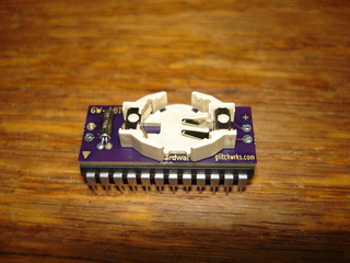
The Sun NVRAM/hostid FAQ covers the general process on replacing the battery in a 48T02, as well as how to reprogram the NVRAM once it is repaired. Many users attach a battery pack with flying leads, or glue a coin cell (directly or in a holder) to the top of the module, similar to my Dallas DS1387 rebuild. The remote pack is necessary at times due to height restrictions in some Sun systems – in the SPARCstation 2, for instance, the NVRAM is located under a SBus slot, and gluing a cell holder to the top of the NVRAM would prevent a SBus card from being installed there. Since I had many NVRAMs to modify and wanted a cleaner solution, I decided to lay out a small module to hold a CR1225 and a new crystal, completely replacing the “CAPHAT” on old 48T02 modules.
Preparing the Dead 48T02
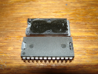
Part of the efficiency in using a replacement module is that the old “CAPHAT” is removed as a single piece. Only two cuts are required, and we intentionally cut through the embedded leads rather than having to try and avoid them. I used a hack saw, but any small cutting tool will work. To begin, saw just above the bottom edge of the “CAPHAT” module, about to the depth of the back of the first and last pairs of pins. Then, insert a small screwdriver and pop the module off.
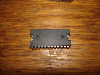
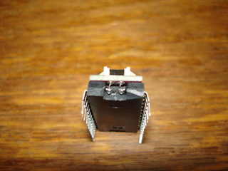
As seen in the second image above, if done carefully, four contacts will remain, sticking up from the ends of the 48T02 IC. These can be soldered directly to the replacement module. If they break off, or if they were cut too short, simply remove the epoxy from the recesses at either end of the IC and clear the embedded forked contacts in the chip body:
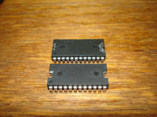
Here’s a picture with the two options side-by-side. Leaving usable wire stubs will mean you don’t have to use small jumper wires between the IC and the replacement module, but breaking them off or otherwise removing them doesn’t mean the module is dead, as several existing writeups have suggested:
Assembling and Installing the Replacement Module
If you’ve ordered assembled replacement modules from us, you can skip the module assembly bits and go directly to installation. If you’ve purchased a panel or partial panel of bare modules from us, or had your own modules fabricated from our Gerber files, you’ll need to install the coin cell holder, 32.768 KHz crystal, and jumper wires (if you fully removed the old pins).
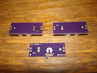
To assemble the modules, solder the coin cell holder to the board, and then the crystal. Make sure to keep the crystal flat against the module. Once soldered, cut the leads as flush to the board as possible – use flush cutters if you have them. If you don’t have flush cutters, or the cuts stand proud, dress them down with a file or grinding tool (such as a cutting disc on a Dremel tool). Here’s a picture of a bare module with two assembled modules. The assembled module on the top-left has the pins intact, the one on the top-right has had the pins cut flush with the bottom of the board:
At this point, you can solder in the jumper leads, if required. The jumpers can be installed after gluing, as well. The module should be glued to the top of the 48T02 IC rather than just using the jumper leads to support it. I used two part epoxy with a 5-minute curing time for this. Cyanoacrylate glue (superglue) would also work, but won’t be as durable. Apply a small amount of glue to the middle of the IC, and align the replacement module. Allow sufficient curing time before proceeding. Apply a small dab of glue to the oscillator crystal, attaching it to the circuit board of the replacement module. Once the glue has set, solder the jumper wires. Pictured is a close-up of replacement jumpers, used when the 48T02 IC is completely stripped of the old “CAPHAT” wires:
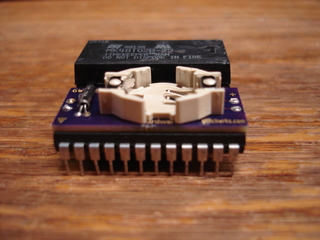
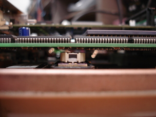
Measurements taken on completed modules showed that the GW-48T02-1 replacement is approximately 1.25 mm (approximately 0.050 inch) taller than the original 48T02. This is adequate for installation under SBus boards, as in the SPARCstation 2. Below is a side-by-side comparison, as well as a picture of the GW-48T02-1 installed in a SPARCstation 10 (it’s not compatible with the SS10, this was only done for clearance testing):
Installation in Sun Systems
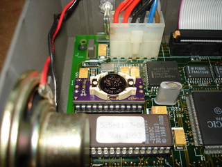
Finally, insert a CR1225 into the coin cell holder, and install the GW-48T02-1 in your Sun system. Note that pin 1 is marked with a triangle on the GW-48T02-1. The completed module does fit within the AMP extractor commonly found in Sun systems (replacements do not, they’re wider). Here’s the GW-48T02-1 installed in a SPARCstation IPX:
Do note that this module can be used to repair any 48T02 with a “CAPHAT” module, including those found in non-Sun equipment. While it should be possible to rebuild fully potted 48T02s using this module, it will be much more difficult, as the entire IC is enclosed in a potting shell, filled with potting compound.
NVRAMs repaired

