Topic: Replacing a dead lithium cell in the DS1387
Date: 2017 JUL 27
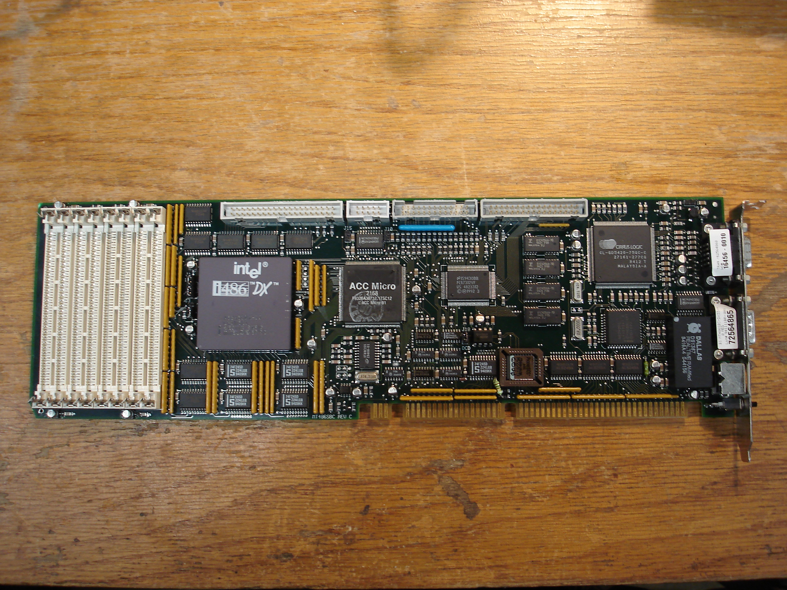
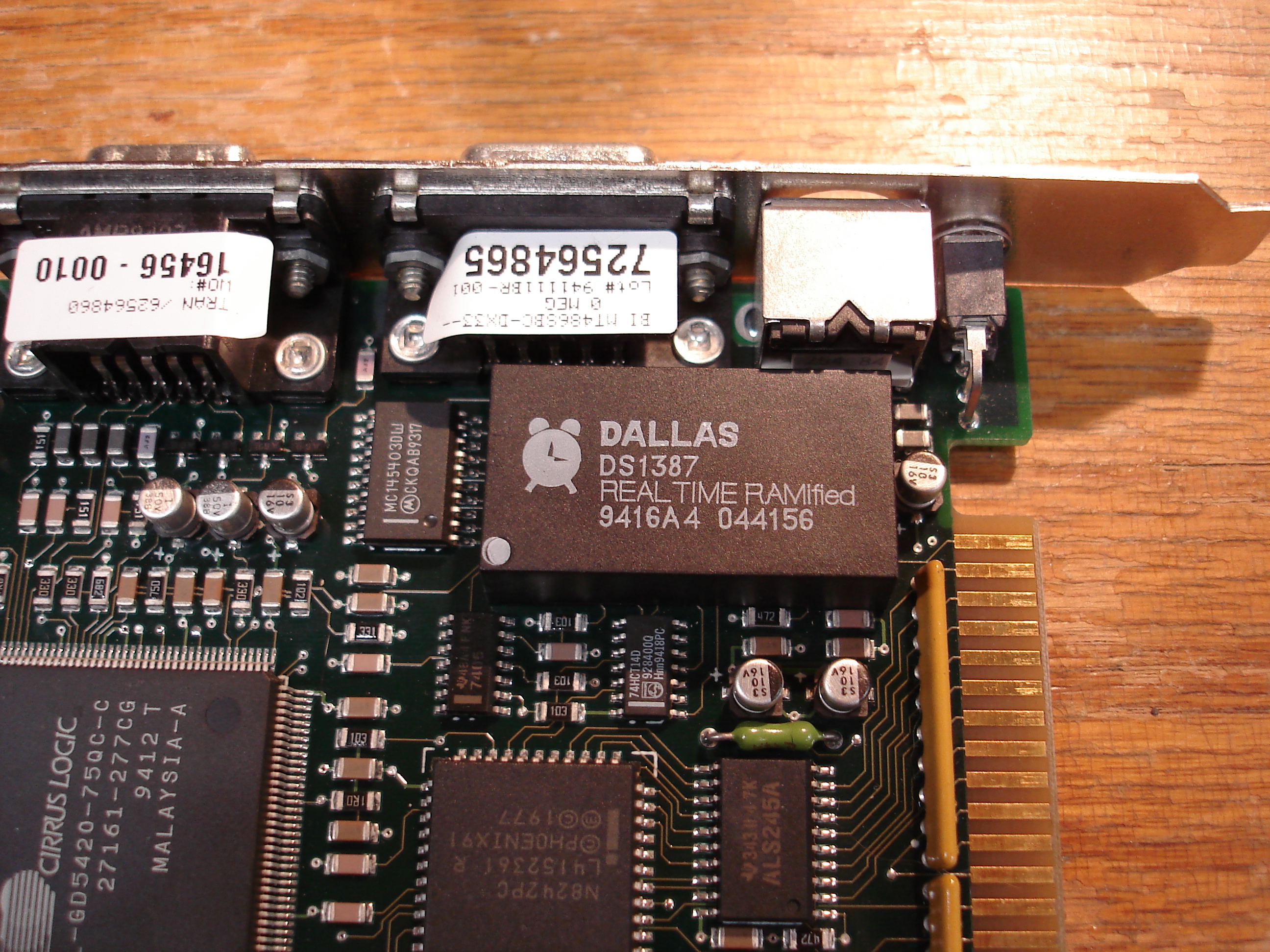
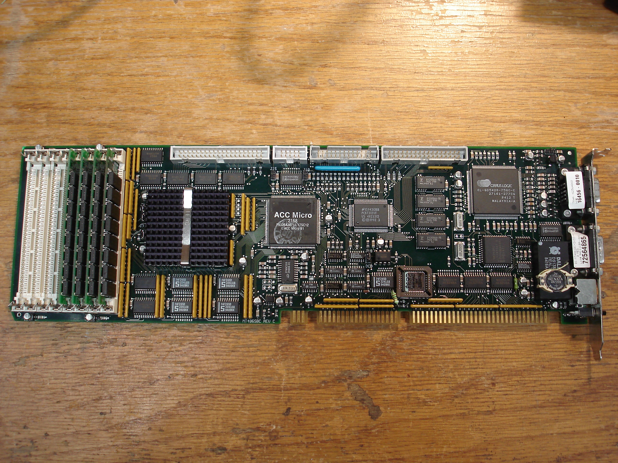
While most PCs use a RTC/CMOS chip that has an external battery, many industrial x86 computers use RTC/NVRAM modules. They’re convenient when new, since the battery and RTC crystal are encapsulated into the module. The module’s potting keeps the lithium cell from drying out as quickly in high temperatures, extending its life. Since the cell is potted, in the unlikely event of a cell rupture or leak, the system won’t be destroyed by battery electrolyte. The downside is, the battery eventually dies, and often the NVRAM is used for storing some critical parameter that keeps you from booting. This was the case with the Multitech industrial 486 single-board computer on my bench today: it uses a Dallas DS1387 RTC/NVRAM module, which is similar to the DS1287 but with more NVRAM (4K vs. 114 bytes). Unfortunately, the DS1387 has no currently available replacement. The chip used in the module was produced as a bare IC, requiring external battery and crystal, but that part is also no longer available.
Others have repaired DS1387 modules in the past, and posted writeups to the Internet. I used the following two writeups as a guide in my repairs:
For the repairs, I used:
- Renata HU1225-LF through-hole CR1225 holder
- Renata CR1225 3V lithium cell
- Small piece of 28 AWG Kynar wire
- Kester 63/37 leaded solder
- Cyanoacrylate glue (superglue)
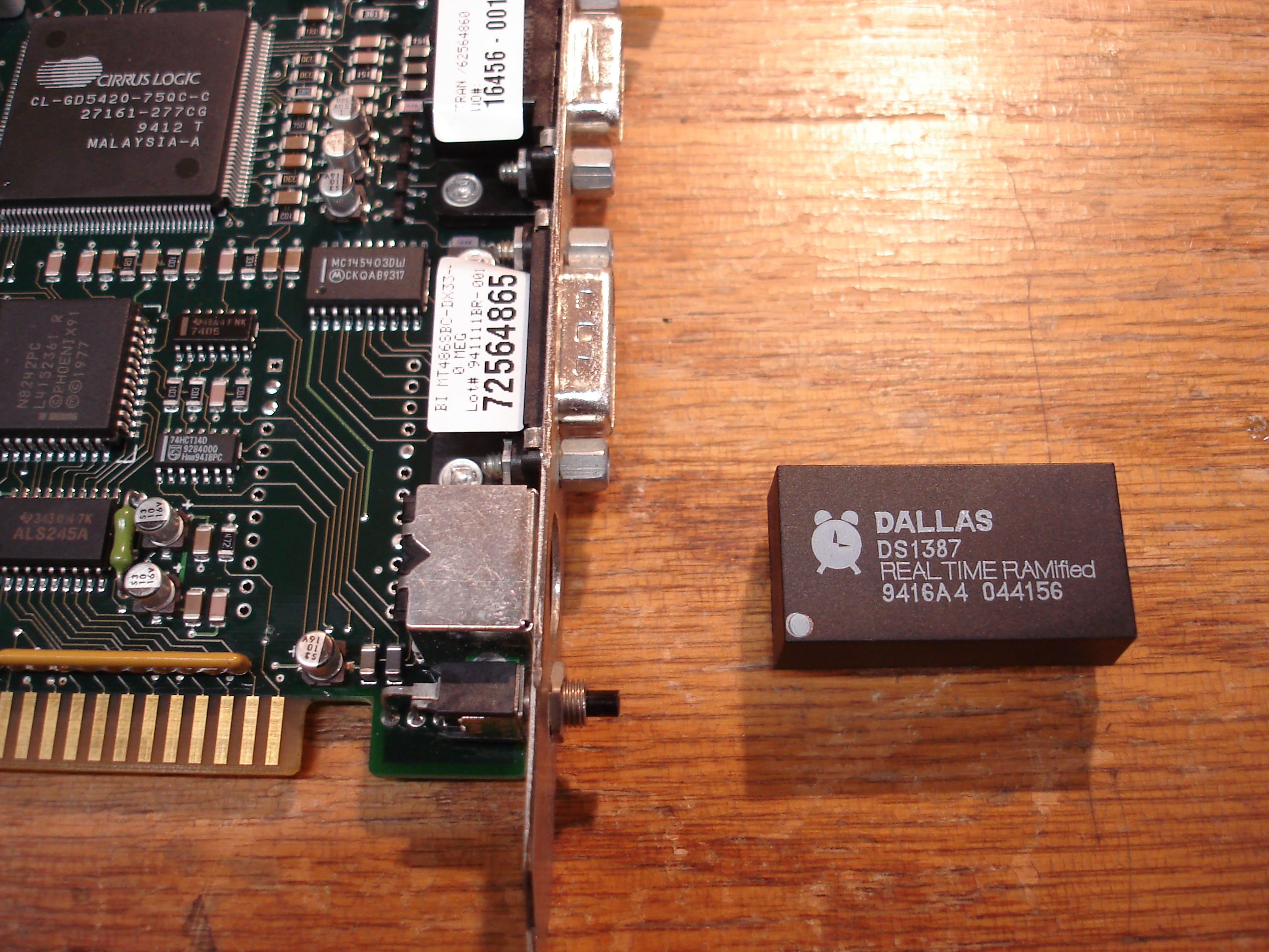
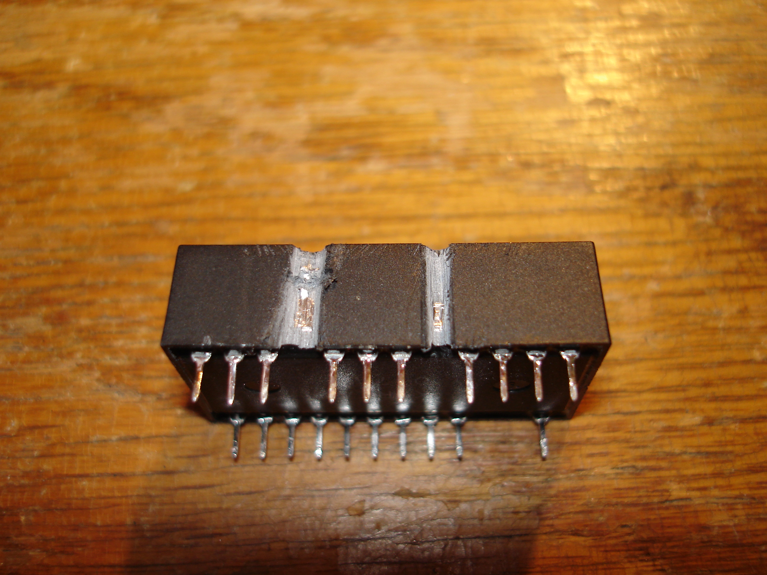
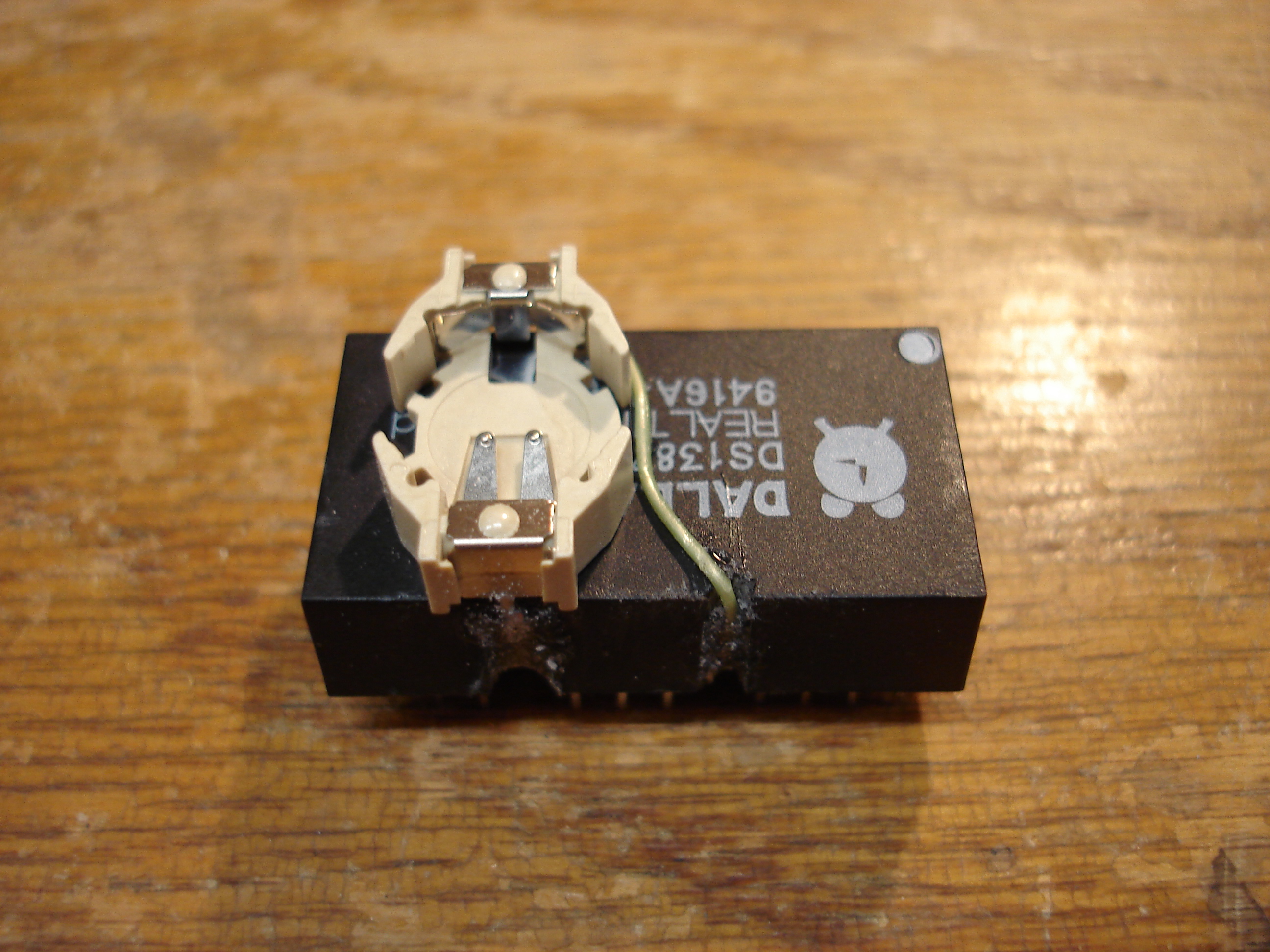
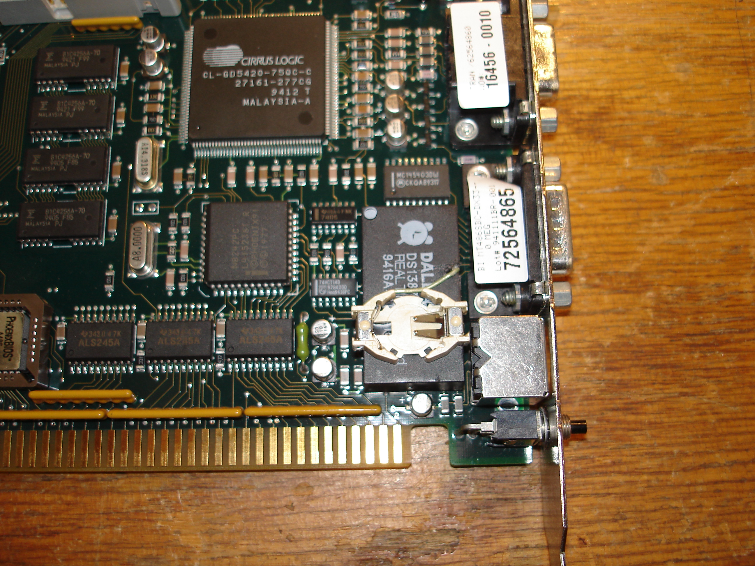
My approach is slightly different than the linked writeups. I had very little room to work with, since the SBC plugs into an ISA slot with standard spacing from the next slot – too tall of a replacement battery would contact a board in the next slot. The side requiring cuts to access the buried terminals was almost against ports on the SBC’s connector end, as seen above. The first step was to desolder the module, and start opening up the potting shell. I made slow cuts with a hack saw, until I felt the blade contact metal pins inside the module:
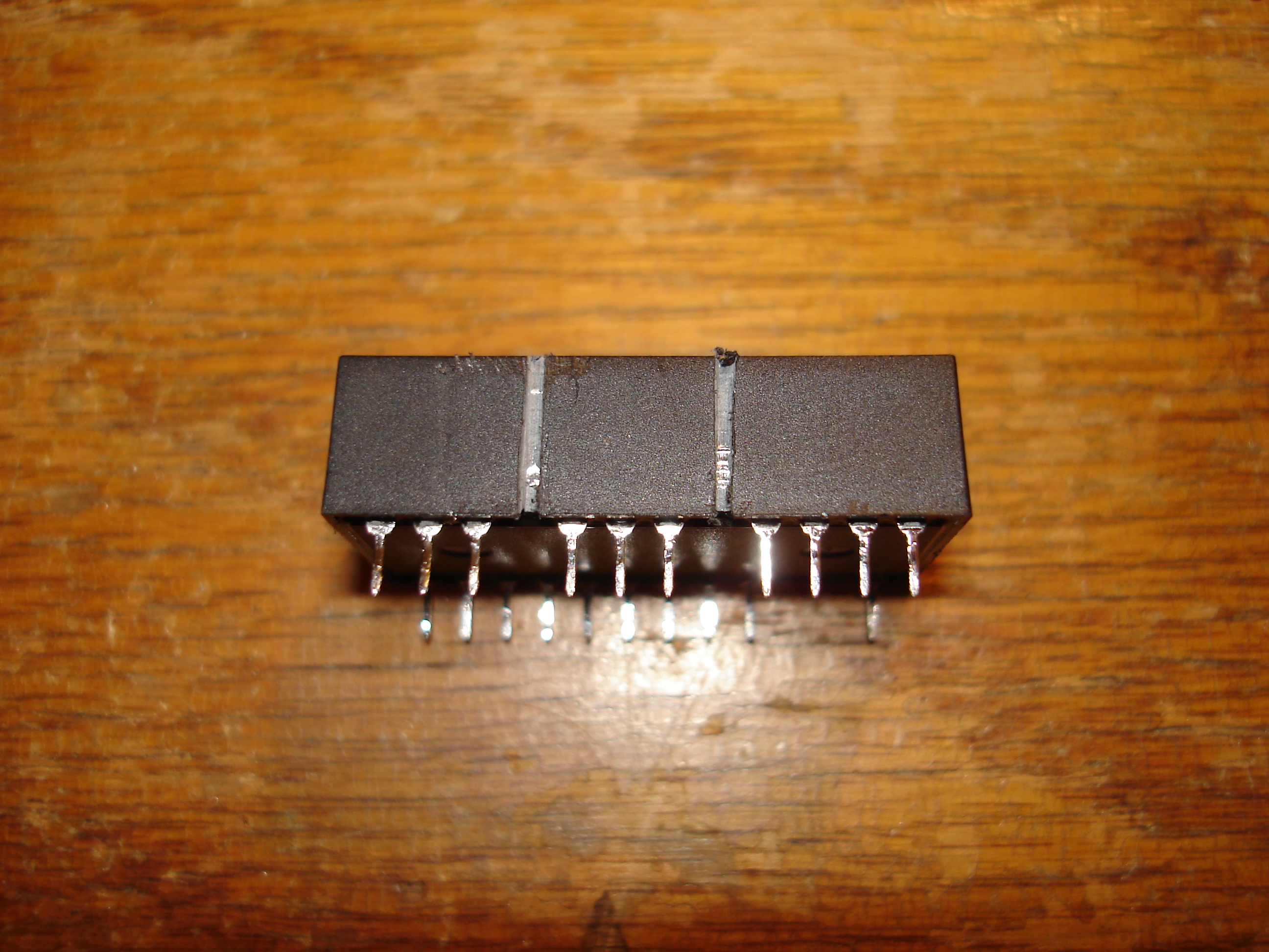
With the pins located and partially exposed, I opened up the cuts with a triangle file. After a bit of filing, it was obvious why the other two guides recommended breaking the ground connection rather than the positive connection – it stays closer to the surface of the potting for a greater distance, including the tapered down portion of the pin, which makes cutting much easier. I scraped away the last bit of potting compound with a small jeweler’s screwdriver, then drilled through the ground pin with a small carbide circuit board drill. Zooming in on the following images will explain better than words:

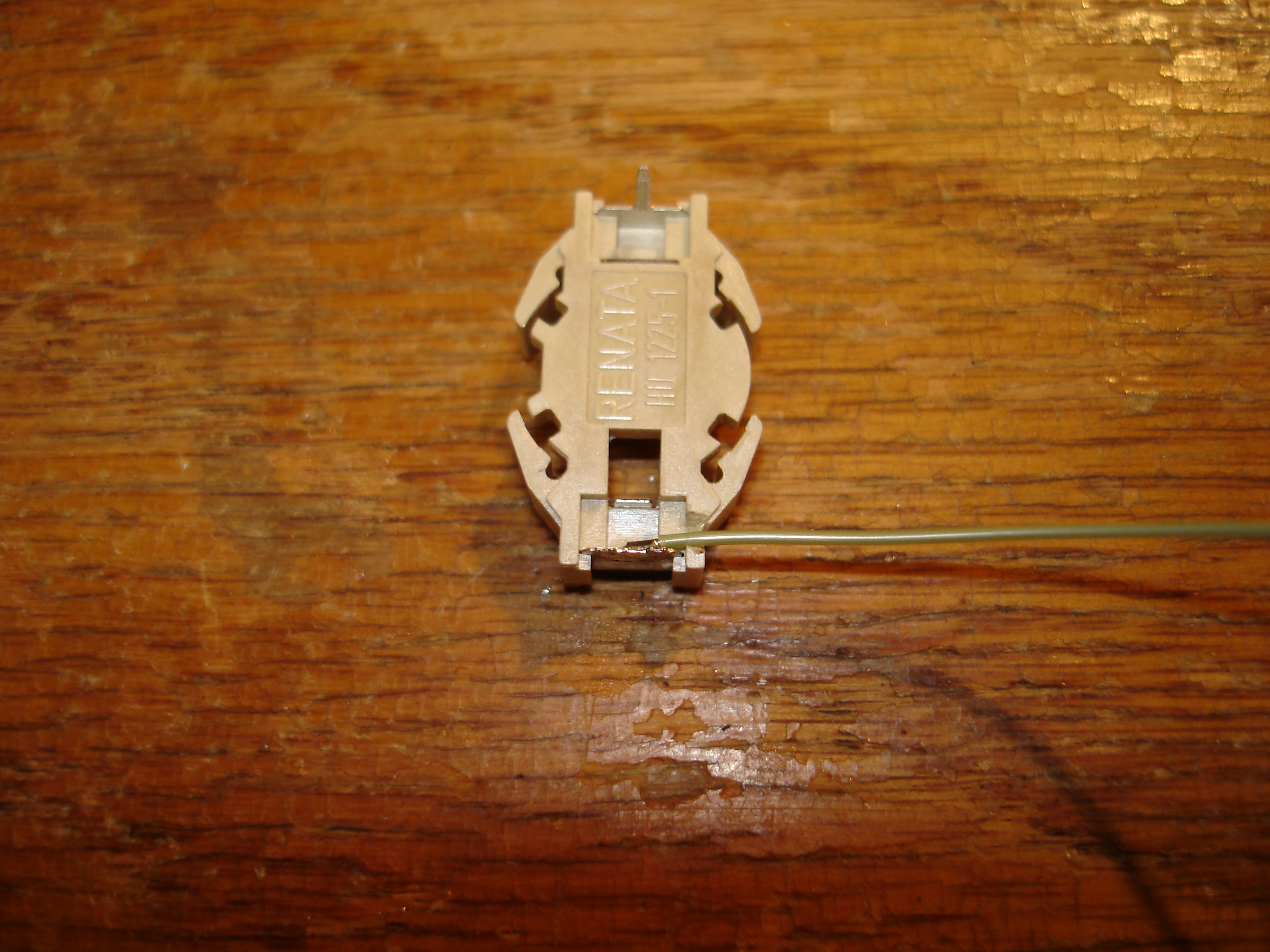
I used a Renata HU1225-LF through-hole CR1225 cell holder for the repair. The CR1225 is much smaller than the more common CR2032, but is still cheaply and readily available from the usual sources. I cut the positive terminal’s through-hole pins off, made a small notch in the holder’s case, and soldered a length of 28 AWG Kynar wire to the terminal. The notch lets the holder sit flush against the module while allowing the wire to pass under it. The holder was then attached to the module with cyanoacrylate glue (superglue) such that the negative through-hole pin was over the exposed negative pin on the module:
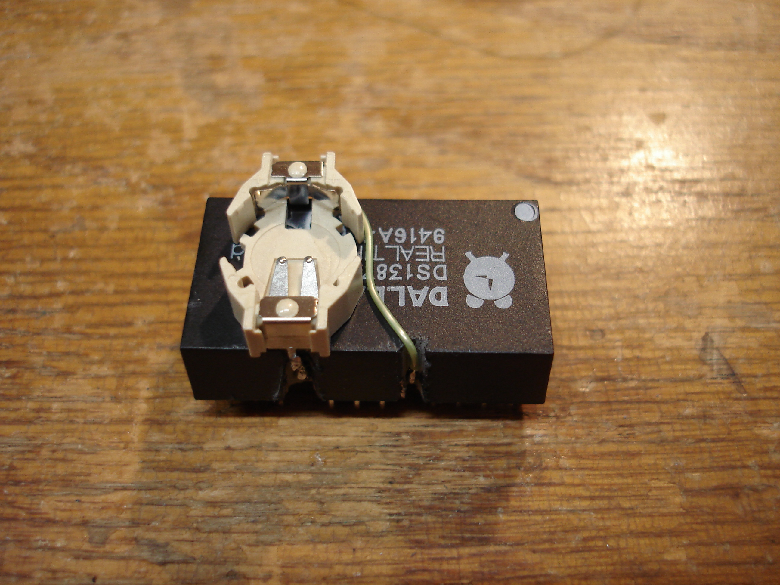
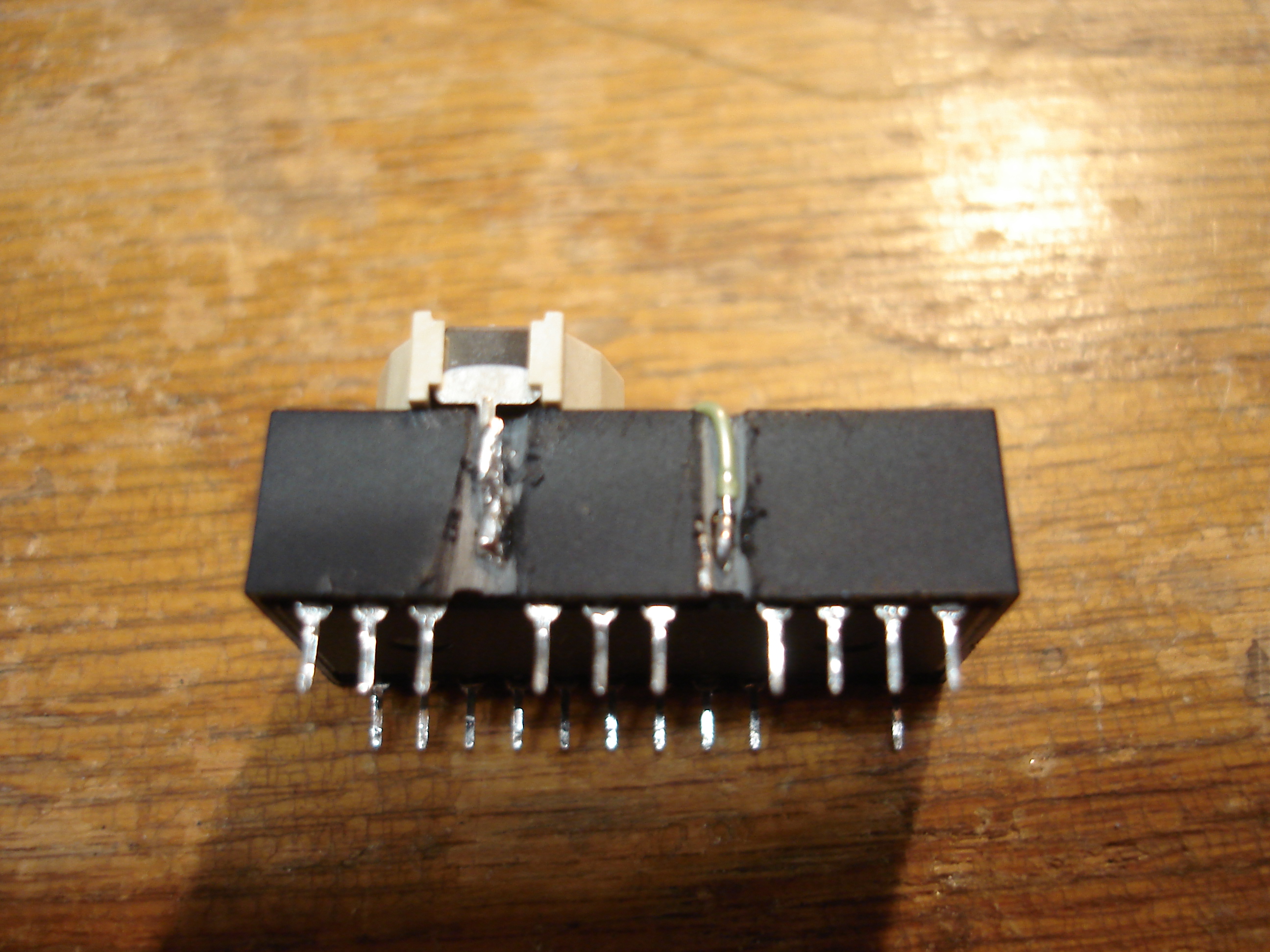
The holder’s negative pin and the flying positive lead were then soldered to the exposed terminals. Be sure to use an adequately large iron tip as the negative terminal sinks a lot of heat. Don’t accidentally reconnect the cut negative battery pin! The flying lead was tacked down with a little more superglue, and the exposed leads were given a coat. If you’re in a hurry, a pinch of baking soda makes superglue cure almost instantly.
The module was reinstalled in the 486 SBC and a CR1225 battery was inserted into the holder:

That’s it! With the RAM and heatsink reinstalled on the SBC, the CMOS settings and date/time were set, and the machine was powered off. All settings were retained, and the clock continued to run with the power off, so the rebuild was a success!
clock modules rebuilt