Topic: Hacking on a RP2350 Z80 board
Date: 2026 JUL 13
I picked this board up in a large lot of industrial scrap we’d purchased for one or two specific items in the lot. The board looked old and interesting enough to hack on, rather than just stripping it for its parts. It was obviously a fairly complete Z80 single-board computer. Here’s basically how it arrived to us, though I did straighten the heatsink fins before taking pictures:
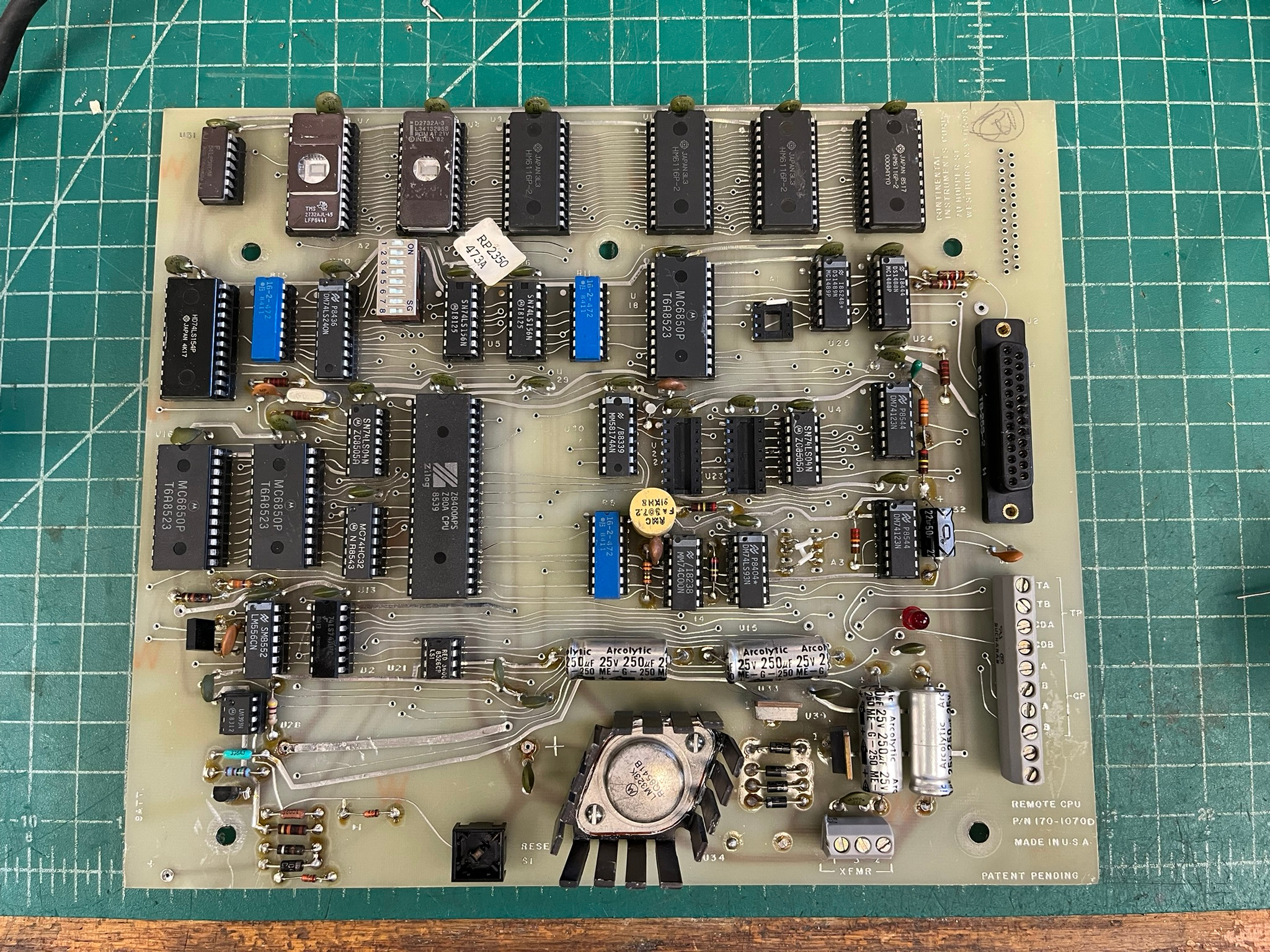
The board is manufactured by Continental Instruments Corp., was marked as a REMOTE CPU, and carries the part number 170-1070D. There wasn’t a model number listed in the copper, but there was a little paper sticker floating around with RP2350 and 473A on it. Since I have nothing better to go on, I’m assuming RP2350 is the product/model number, and 473A is the serial number. Here’s the information in the copper layer:
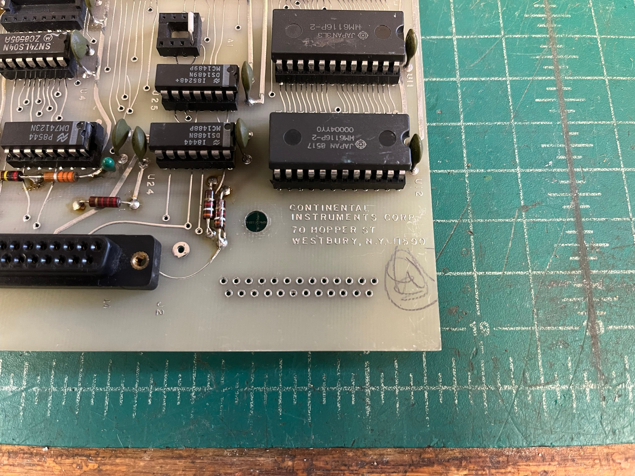
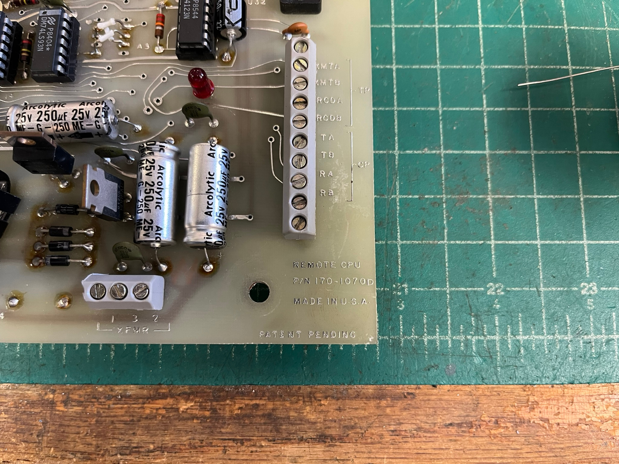
I can’t find much information about this board online. Continental Instruments Corp. in Westbury, NY appears to have been an alarm system manufacturer, since bought and sold several times. I suspect this board was part of an alarm controller, but have not found definitive evidence. RP2350 is now a Raspberry Pi part number, which makes searching more difficult! If you have information on this board, please contact me!
Initial Repairs and Cleanup
First step was a general cleanup and recap. There were several broken ceramic disc capacitors, which were replaced with similar looking parts from inventory. One footprint was too narrow (the original had its legs bent in, too), and was replaced with a modern MLCC radial capacitor. Electrolytics were replaced with convenient values on-hand: the 250uF 25V parts were replaced with 470uF 40V Vishay capacitors, and the missing bulk electrolytic was replaced with a 10000uF 16V Illinois Capacitor part.
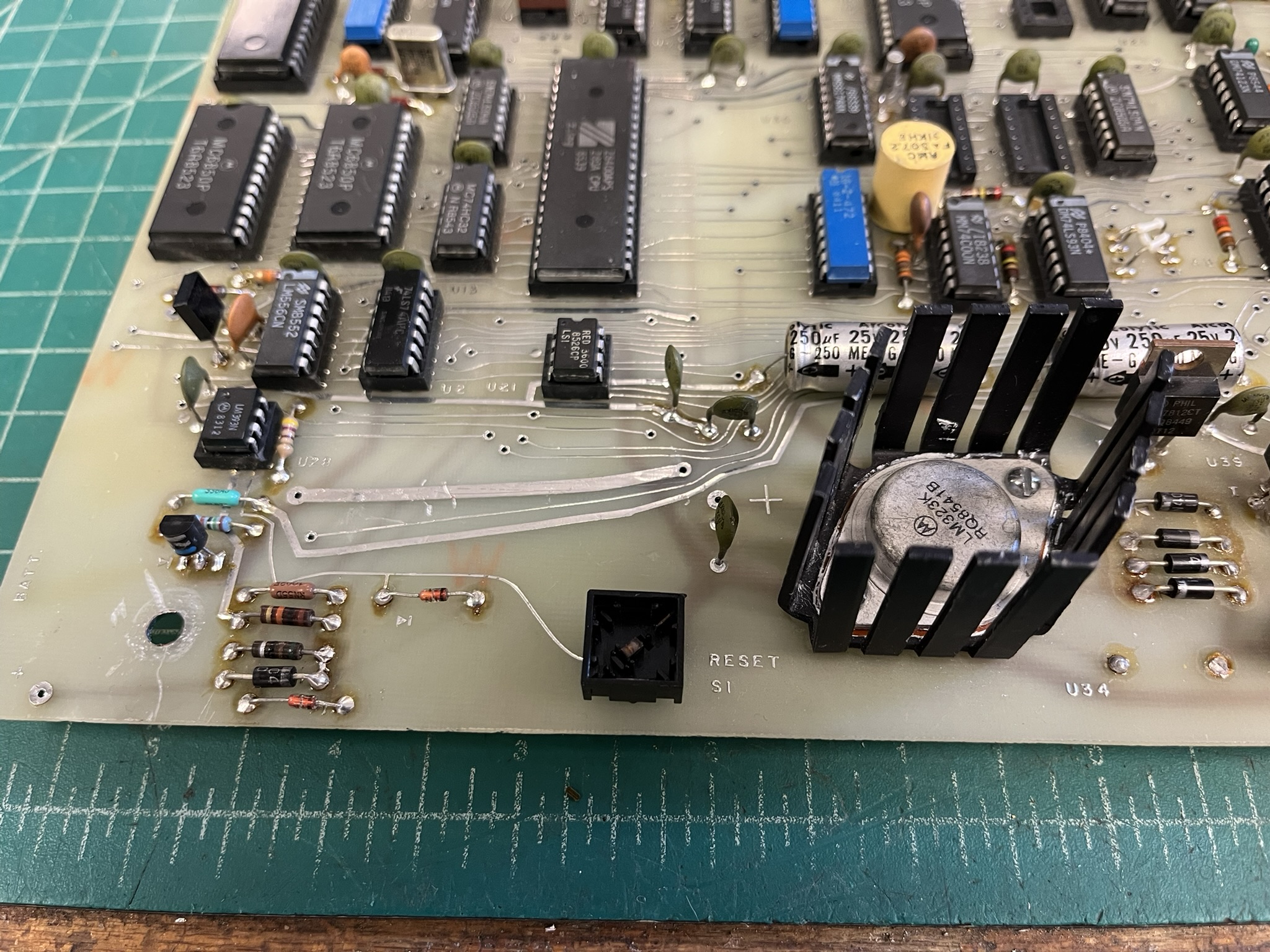
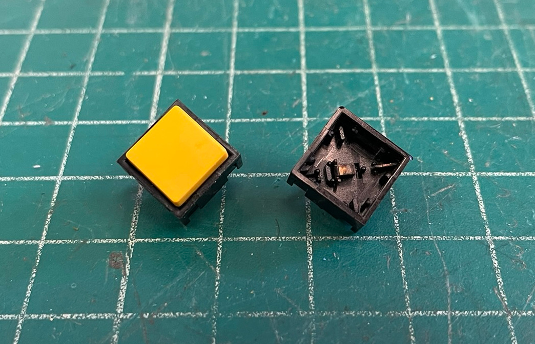
The reset switch had been broken during the board’s time in the scrap lot it came from:
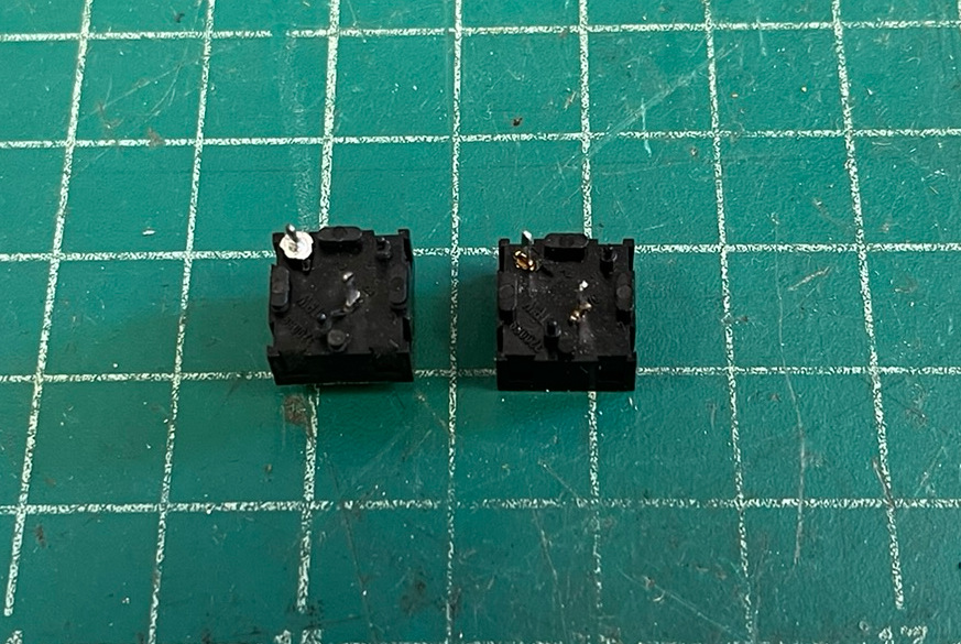
As luck would have it, the PCB MOUNT PUSHBUTTONS drawer had an exact match with a yellow key:
I wanted to refresh the +5V regulator’s thermal paste, and also reverse the mounting screws. The board was originally assembled with the heads of the screws on the top side of the board. This leaves the nuts, washers, and tails of the screws sticking down, which makes the board sit unevenly on the workbench:
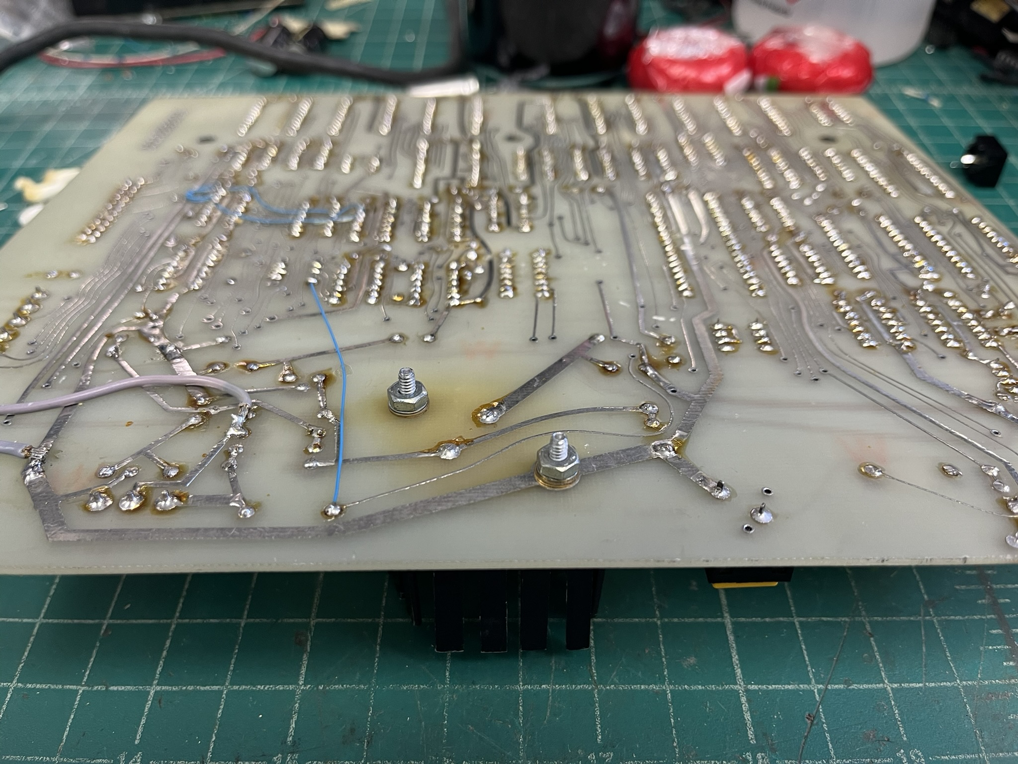
I reused the screws, but did add internal tooth lock washers for better contact. On this regulator, the TO-3 case is ground.
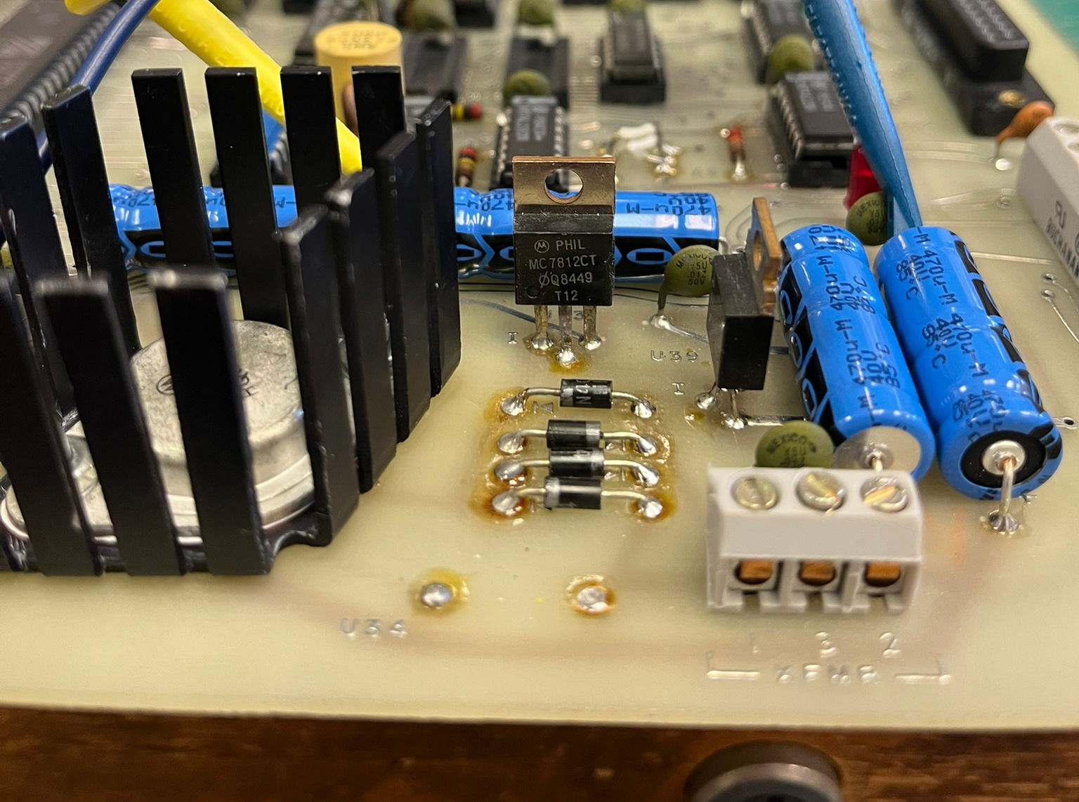
Before power-up, I traced out the power circuit and determined that the bulk capacitor was providing not just the unregulated rail that became +5V, but also +12V was regulated down from the same rail! That explains the rather large heatsink for a board that should draw under an amp. I removed the +12V regulator temporarily so that the board could be powered by a triple-voltage power supply, with less heat generation:
At this point, we’re ready to apply power. I decided to dump the EPROMs first, and run them through the disassembler.
Firmware and System Architecture
The ROM dump proved useful. There was a string, RP Zap, and parts of the general structure of the firmware which suggested to me that it may contain a derivative of the popular ZAPPLE monitor, a ROM monitor written for the Z80 by Technical Design Labs (TDL) in the 1970s. I have hacked on the Zapple monitor extensively in S-100 systems.
The dumps of the original firmware can be found on the Glitch Works Filedump:
The above are both Intel HEX format, and are also available via FTP.
With a serial cable hooked to the DB25F on the board, and cabled to a PC running minicom (a terminal emulator), I was able to get the board to come up and print RP Zap. I couldn’t get it to accept any other commands. After several hours of disassembly work, I decided that it probably was waiting on a specific handshake to upload firmware from the main processor – it was, after all, a REMOTE CPU in whatever system it came from. I decided I had enough information to customize GWMON-80 for the RP2350.
GWMON-80 customization was fairly easy, as I had the general memory layout from the disassembly, as well as the console ACIA’s I/O base address of 0x20. GWMON-80 looped on powerup, printing the signon and prompt over and over, about once a second. The red LED on the RP2350 also flashed. I suspected that I had run into a watchdog timer which was not being fed. I traced back from the Z80’s *RESET pin, and found that there was indeed a watchdog signal being generated, and that it was muxed with the pushbutton reset by U13, a 74HC32 quad 2-input OR gate. Lifting the pin on the 74HC32 that the watchdog drove stopped the boot loop, though it also prevented automatic power-on reset, requiring me to press the RESET button to bring up GWMON-80.
With GWMON-80 running, I was able to map out the I/O space of the board:
  I/O Map
  =======

  74LS154 at U19 splits I/O space into 16 blocks, 16 ports per block:

  0x00 U16 ACIA base
  0x10 U17 ACIA base
  0x20 console ACIA base
  0x30 unused?
  0x40 switch register, closed = 1
  0x50 RTC base
  0x60 unused?
  0x70 watchdog port, reads or writes keep it fed
There’s exactly one instruction in the original firmware that accesses I/O ports between 0x70 and 0x7F: an IN instruction in the RST7 IRQ handler. I suspected there was a periodic interrupt being generated and fed into the Z80’s *INT line, as the firmware set up a RST7 handler, put the Z80 in interrupt mode 1, and enabled interrupts. I updated the GWMON-80 customization to do the same:
;;;;;;;;;;;;;;;;;;;;;;;;;;;;;;;;;;;;;;;;;;;;;;;;;;;;;;;;;;;;
;Hardware Equates
;;;;;;;;;;;;;;;;;;;;;;;;;;;;;;;;;;;;;;;;;;;;;;;;;;;;;;;;;;;;
CTLPRT	equ	020H		;Console ACIA control port
DATPRT	equ	021H		;Console ACIA data port
WDTPRT	equ	070H		;Watchdog timer port
STACK	equ	03FF0H		;Stack at the top of RAM

;;;;;;;;;;;;;;;;;;;;;;;;;;;;;;;;;;;;;;;;;;;;;;;;;;;;;;;;;;;;
;Reset and Interrupt Vectors
;
;This board issues a periodic interrupt to the CPU which is
;necessary for feeding the watchdog timer.
;;;;;;;;;;;;;;;;;;;;;;;;;;;;;;;;;;;;;;;;;;;;;;;;;;;;;;;;;;;;
	ORG	0000H
RESVEC:	JMP	CSTART		;RST0, system reset vector

	ORG	0038H
IM1VEC:	JMP	IM1HND		;RST7, interrupt vector for IM1, periodic
				;interrupt on this system

;;;;;;;;;;;;;;;;;;;;;;;;;;;;;;;;;;;;;;;;;;;;;;;;;;;;;;;;;;;;
;IM1HND -- IM1 interrupt handler
;
;This routine handles RST7 hardware interrupts when running
;in Z80 interrupt mode 1. On this board, the interrupt is
;triggered via periodic timer.
;;;;;;;;;;;;;;;;;;;;;;;;;;;;;;;;;;;;;;;;;;;;;;;;;;;;;;;;;;;;
IM1HND:	DI			;Disable all interrupts
	PUSH	PSW		;Save PSW, A on stack
	IN	WDTPRT		;Feed the watchdog
	POP	PSW		;Restore PSW, A
	EI			;Enable interrupts
	RET

	ORG	0100H		;Leave room for RSTn vectors, handlers

	INCLUDE	'vectors.inc'	;Standard GWMON-80 jump table

;;;;;;;;;;;;;;;;;;;;;;;;;;;;;;;;;;;;;;;;;;;;;;;;;;;;;;;;;;;;
;CSTART -- Cold start routine
;
;Configure interrupt mode. Falls through to SM.INC
;
;Function label is defined in VECTORS.INC
;;;;;;;;;;;;;;;;;;;;;;;;;;;;;;;;;;;;;;;;;;;;;;;;;;;;;;;;;;;;
	DI			;Disable interrupts during setup
	db	0EDH, 056H	;IM 1 Z80 instruction
	EI			;Enable interrupts

	INCLUDE	'sm.inc'	;The small monitor
This simply sets up a RST7 handler which saves the A register and processor status word, reads from the watchdog port, restores the A register and PSW, re-enables interrupts, and returns. The cold start routine then sets up the Z80 for interrupt mode 1, which requires inlining the opcode as hex data, since GWMON-80 is assembled on the A85 assembler.
The above works fine, and GWMON-80 now runs with the watchdog enabled. The red LED on the RP2350 remains lit during operation, as with the original firmware. Should you wish to build GWMON-80 for a RP2350, the make target rp2350 will build the small monitor.
Switch Pack Replacement
There was one last minor repair: the switch pack at A2 was broken and needed replaced:
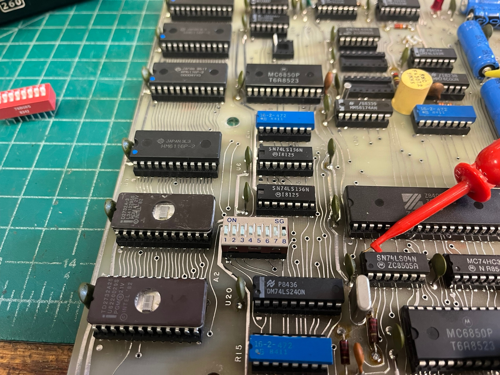
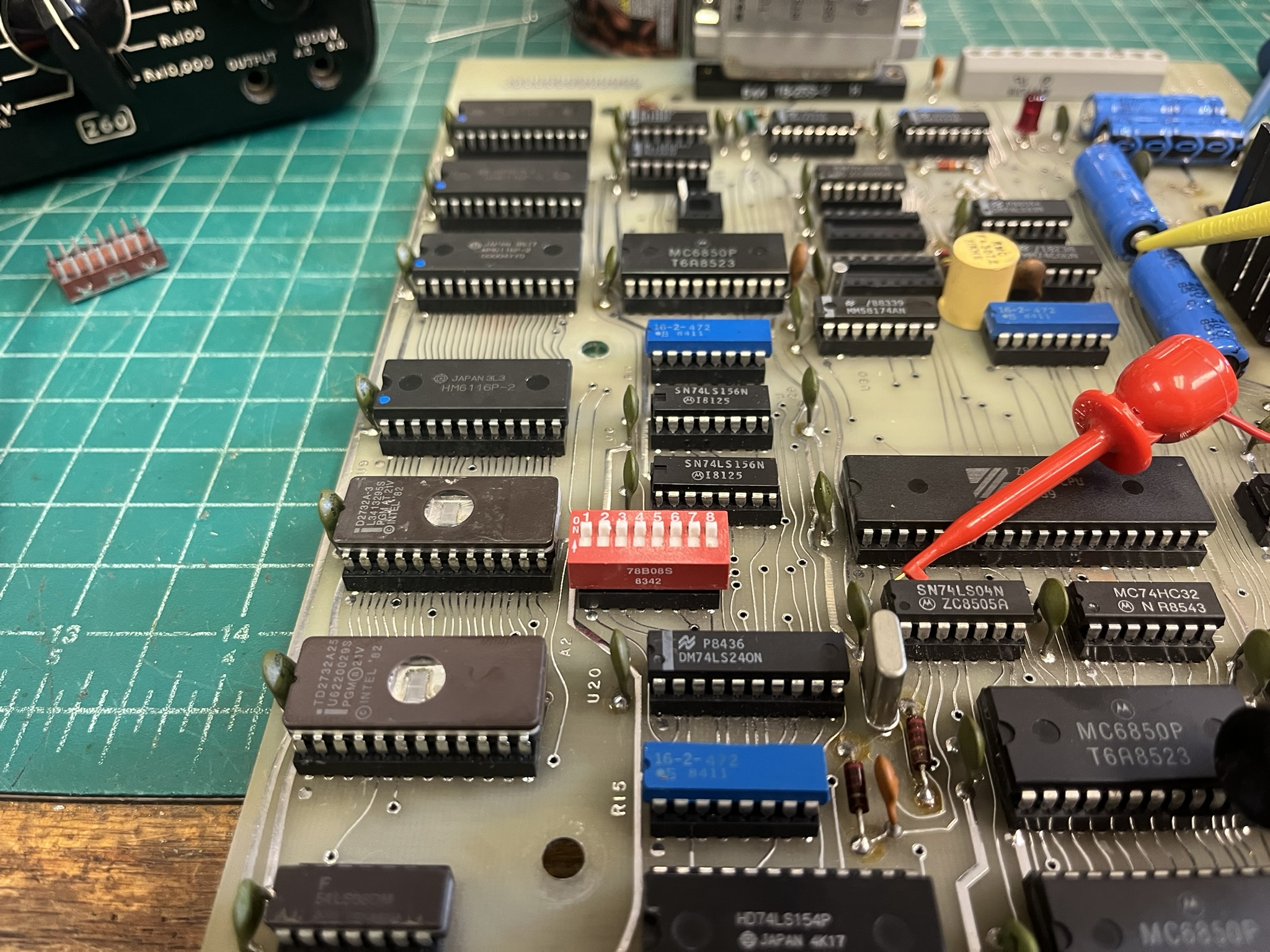
I originally plugged the new DIP switch into the same socket the old one had been in, but ended up with a different stuck bit in the switch register. This turned out to be a broken pin inside the TI low-profile socket. The socket was removed, and the new DIP switch soldered directly to the board.
Future Hacking
I’m not sure what I’ll do with this board. It’s a fairly complete SBC, with the following:
- Z80 processor at 4 MHz
- 8K EPROM, 2732 type devices
- 8K static RAM, 6116 type devices
- 3x 6850 ACIAs, one as console with RS-232 level conversion
- MM58174AN microprocessor real-time clock (RTC)
- Battery backup for at least the clock, perhaps SRAM too
- LSI RED3600 for deriving timing from AC line frequency
- 8-bit switch register
- Hardware watchdog timer, triggers reset
- Periodic interrupt on maskable interrupt input
There are two empty sockets at U22 and U23, I have not yet determined their function, but suspect they have to do with buffering or level shifting for the 6850 ACIAs at U16 and U17.
The RP2350 would be better suited with a triple secondary power transformer and some rewiring to accommodate it. Any transformer with enough voltage headroom for the +12V regulator would be running the +5V regulator hot. If I keep the board and run it, I will likely make that modification, using some of the spare positions on the terminal strips.
This board could be easily expanded using the spare DB25 footprint near the manufacturer’s name. The unused I/O selects from U19 could be jumpered to it, along with the data bus and four low address bits. Perhaps it would make an interesting controller for a clock! In any case, a lot more is now known about the RP2350, which will inform any future hacking.
alarm boards repurposed