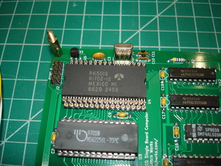
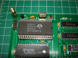
Topic: Designing a SBC for the Rockwell R6501Q/R6511Q
Date: 2024 NOV 04
Quick Links
- Final R65X1Q SBC schematic
- VCFed Forums Design/Build Thread
- Kit Build Video
- R65X1Q SBC kits on Tindie
I learned about the Rockwell R6501Q single-chip microcomputer from Burgess while working at Sontec/ITI Audio during college. Burgess had used it in the Sontec FORTH computer, and had all of the documentation he used to create the design, as well as his personal design experience to share. The R6501Q is essentially a 6502 processor core with onboard I/O, timers, and a small amount of RAM, plus a few additional instructions from the 65C02 family. I acquired several R6501Q processors over the years. Despite all of these neat features and compatibility with a processor whose architecture I already understood, I never actually built anything with them, since breadboarding with a R6501Q is basically impossible: they’re packaged in a QUIP (QUad Inline Package), which is essentially two ZIP footprints!
After getting the Sontec FORTH computer working, and finding that the EPROM contained a copy of Rockwell’s FORTH development system, I was motivated to actually create a single-board computer for the R6501Q, and began laying one out. As VCF East 2020’s virtual date was approaching, I decided to also use the board as the virtual workshop project for the year. I wanted the following features on the board:
- R6501Q at 1 MHz
- 32K static RAM, FeRAM compatible
- 32K EEPROM, paged in 4K segments
- Power-on boot to EEPROM, with support for ROMFS
- Compatible with Rockwell’s RSC-FORTH
- Onboard serial console with RS-232 level shifting
- Unused I/O available on headers
- Glitchbus expansion
Processor Clock and Support
The SBC was to be equipped with a 4 MHz crystal, as the R6501Q has a built-in crystal oscillator, and requires only the crystal and two capacitors. The standard R6501Q divides the 4 MHz clock down to 1 MHz internally, while the R6501AQ divides it down to 2 MHz internally. As long as all support circuitry works at 2 MHz, the change requires no hardware modification.
Reset was to be handled by the excellent DS1233 EconoReset, which is a TO-92 packaged voltage supervisor with pushbutton input. Using an actual supervisor instead of a RC circuit provides guaranteed reset at specified voltage levels, and avoids memory corruption due to errant writes when using NVRAMs. The DS1233 is also open collector output, and can directly drive the Glitchbus reset line. With an external 0.01 uF capacitor, the reset pulse can be lengthened to accommodate some of the old devices that have been interfaced to the Glitchbus.
Address and state decoding for the R6501Q are very simple, being a 6502 core. Everything is qualified by PHI2, which works well with Glitchbus’s *BSTART bus transactions.
RAM
The R6501Q itself contains 192 bytes of on-chip static RAM. This RAM is decoded to live in zero page, from 0x0040 to 0x00FF. On-chip I/O lives below that, from 0x0000 to 0x001F. The gap between on-chip I/O and on-chip RAM is reserved and can’t be decoded externally, effectively making zero page an on-chip only page of memory.
The SBC design includes 32K of static RAM in a JEDEC compatible 28-pin socket. Chip select qualification with PHI2 ensures the address lines are set up before the device is selected, which allows ferroelectric RAM (FeRAM) to operate properly with the R6501Q. The prototype was designed so that the 32K SRAM was addressed from 0x0000 to 0x7FFF, as the Rockwell documentation seemed to indicate that external devices would be completely ignored for zero page access.
EEPROM and Boot
As with the 8085 SBC rev 3, this design was to incorporate a 32K 28C256 type EEPROM, accessed in 4K segments, addressed at 0xF000 through 0xFFFF. This configuration provides more available RAM, and is compatible with ROMFS. Since the R6501Q includes onboard parallel I/O, a few bits of it were used to control EEPROM page selection. Part of PORTC was already being used for extended address lines with the R6501Q in a “Full Address” configuration, so PORTC bits 0, 1, and 2 were used to select the ROM segment, and bit 3 was used to enable or disable the ROM.
On reset, the R6501Q onboard I/O comes up configured as inputs, and with internal pull-up resistors, PORTC gets pulled high. Conveniently, this allows easy boot control for the EEPROM: the ROM enable signal just needs to be active high, and the boot block needs to reside at the highest addresses in the EEPROM, since that’s where the 6502 fetches its reset vector.
Console Serial Port
The R6501Q includes an onboard UART, which was the obvious choice for console I/O. Bitrates are software controlled, using the built-in Counter A channel. When used as the serial bitrate generator, Counter A is forced to run at the PHI2 clock rate, which does limit bitrates. It is not possible, for instance, to generate a reliable 9600 BPS serial clock with a 1 MHz PHI2 clock, the available frequencies are too far out of spec for most serial terminals.
Onboard serial is of course TTL, and the levels were shifted using a MAX232 to RS-232 levels. The RS-232 level signals were brought out to a 5-pin Molex KK-100 connector with the same pinout as used on the 8085 SBC rev 3. RTS and CTS are not used on the SBC, but they are buffered through the MAX232 so that they could be jumpered to unused I/O pins, if desired.
Options Selection
An 8-position DIP switch was included in the prototype, which provides option selection as follows:
- Write protect for the EEPROM
- Console bitrate selection
- Choice of ROM program to load at boot
EEPROM write protect was accomplished by simply isolating the EEPROM’s write pin when the switch was open, and pulling it up with a 4.7K resistor. Six other positions in the DIP switch are wired to PORTA bits 0 - 5, with pulldowns, such that an open switch position reads 0. This software switch register allowed maximum flexibility for the prototype.
One position in the DIP switch is unused.
Parallel I/O
The above features used parts of PORTA and PORTC, but PORTB and PORTD were both completely unused. These ports were brought out to 10-pin headers (the other two pins are grounds) near the edges of the SBC. This seemed to be the most flexible option, as PORTD is capable of tristate operation, whereas the other ports are not. The use of PORTA pins for option selection did limit PORTB to general I/O only: its latched mode of operation requires PORTA bit 0 to operate as the input data strobe.
Glitchbus Expansion
Glitchbus was very easy to adapt to the R6501Q – one of the Glitchbus design requirements was, in fact, easy 6502 interfacing! SBC RAM can be masked with the *BMASK signal, though of course the RAM internal to the R6501Q cannot. *BSTART is simply the inversion of PHI2. BR**W is buffered from the R6501Q’s read/write line. Address data is fully buffered with always-on drivers. The Glitchbus data lines are read or written depending on the state of the read/write line when no on-SBC devices are being addressed.
Supporting Glitchbus I/O addressing did require a little special consideration: Glitchbus includes a line, BIO**M, which indicates whether the bus transaction is for memory (logic low) or I/O (logic high) devices. This works well with the 8080/8085 concept of separate I/O space, which provides a separate 256-byte address space just for I/O devices by using special IN and OUT instructions. The 6502 uses memory-mapped I/O, so there’s no direct equivalent. Instead, a 256-byte page of memory space was decoded as I/O, from 0xEF00 to 0xEFFF (the page below EEPROM). Within this dedicated I/O page, the BIO**M line is driven high, indicating an I/O transaction.
Designing a Prototype Board
With the above in consideration, a prototype board was laid out in KiCAD. Here are the results:
The prototype board worked without modification with my R6501Q! There were a few software issues, but nothing that required a change in board layout: TangentDelta helped with the initial port of Steve Wozniak’s 6502 ROM monitor to the R6501Q by customizing a simulator he’d written for the 6502. There was a mistake made with the bitrate generation, and an incorrect assumption about external RAM being available between on-chip I/O and RAM. Both of these were easily corrected. Having the simulator available before the prototype boards were even finished was a huge benefit!
One of the issues with designing a SBC for the R6501Q was, of course, the processor socket. We tried several kinds of machine pin socket strips with varying grip strength, as well as NOS single-wipe sockets Burgess still had in the stockroom from the Sontec FORTH computer project. All sockets ended up mangling pins on the R6501Q on extraction. It was not easy to get the chip seated to begin with. In the end, we decided that soldering the CPU without a socket was the best approach; however, the prototypes were built up using the machine pin strips:
In addition to the R6501Qs I’d bought over the years, I also had a couple R6511Qs. These are very similar one-chip microcontrollers, with two key differences: the I/O lacks internal pullups, and the clock circuit divides the input by two, instead of by four. From the datasheet, it looked as if simply adding four pull-up resistors would make the board compatible with the R6511Q, so this was tried on a prototype:
This worked, and so the SBC was renamed the “R65X1Q SBC” to indicate it was compatible with both processors.
Both prototypes were tested with a Glitchbus 8255 PPI board, to begin verifying Glitchbus compatibility:
The 8255 PPI board worked as expected! As described above, Glitchbus defines a 256-byte I/O space, compatible with the I/O space used by the Intel 8080/8085, which the 8255 PPI board uses for addressing. Testing the 8255 PPI board with the R65X1Q SBC demonstrated that correct BIO**M generation was happening.
Production Board and Kit
With the minor changes required to support the R6511Q on the same SBC, the R65X1Q SBC production etch was run and tested:
This board worked correctly without modification. An update was made to the BOM, specifying 220R pull-down resistor packs, to deal with the variance of integrated pull-up resistors on the R6501Q: current measurements across prototypes indicated that the pull-ups were anywhere from somewhat under 1K to 7K! The original BOM value of 2.2K caused unreliable switchpack reading for some of the R6501Q processors tested.
The above production design was used to create the R65X1Q SBC kit, which was featured in a virtual workshop for VCF East 2020. A trimmed down version of the livestream assembly session for the workshop can be viewed here:
The initial software load consisted of our ported enhanced Woz monitor and Tom Pittman’s TINY BASIC. With the SBC design finalized, TangentDelta and I could begin work on porting ROMFS to the R6501Q and getting RSC-FORTH working on the SBC!
QUIP processors put to use


