Topic: Repairing blowtorch damage from poor component harvesting
Date: 2026 JUL 16
I picked up this early revision AST SixPakPlus on a popular electronic auction site for $10 (plus shipping) in “parts only” condition…due to someone having harvested components from it using a blowtorch and poor technique:
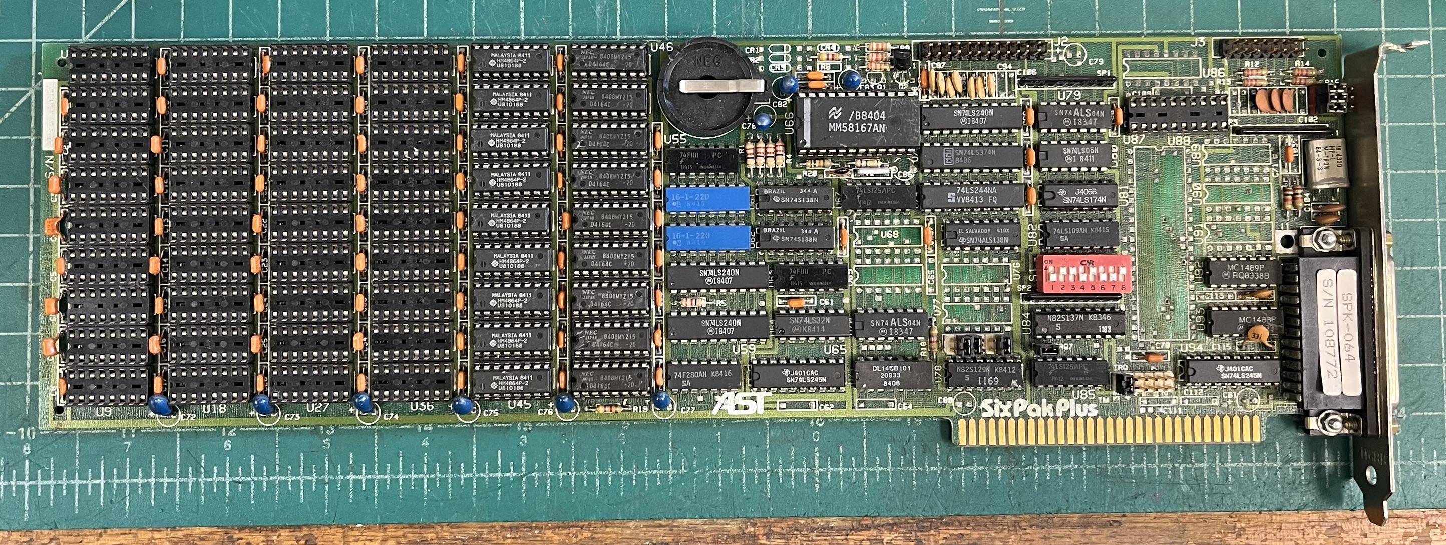
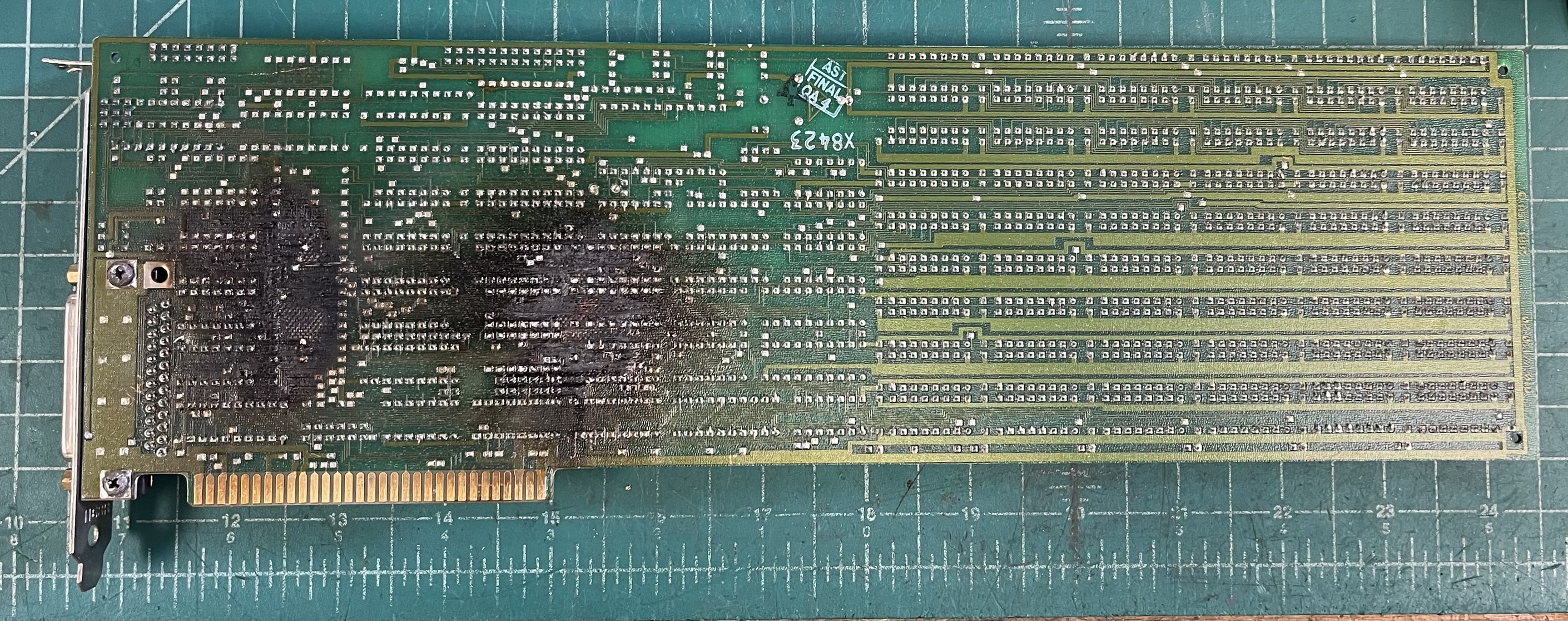
The above images are the board as received, minus a big strip of green masking tape across the RAM area stating it was for parts only. The blowtorch work on the back was pretty rough:
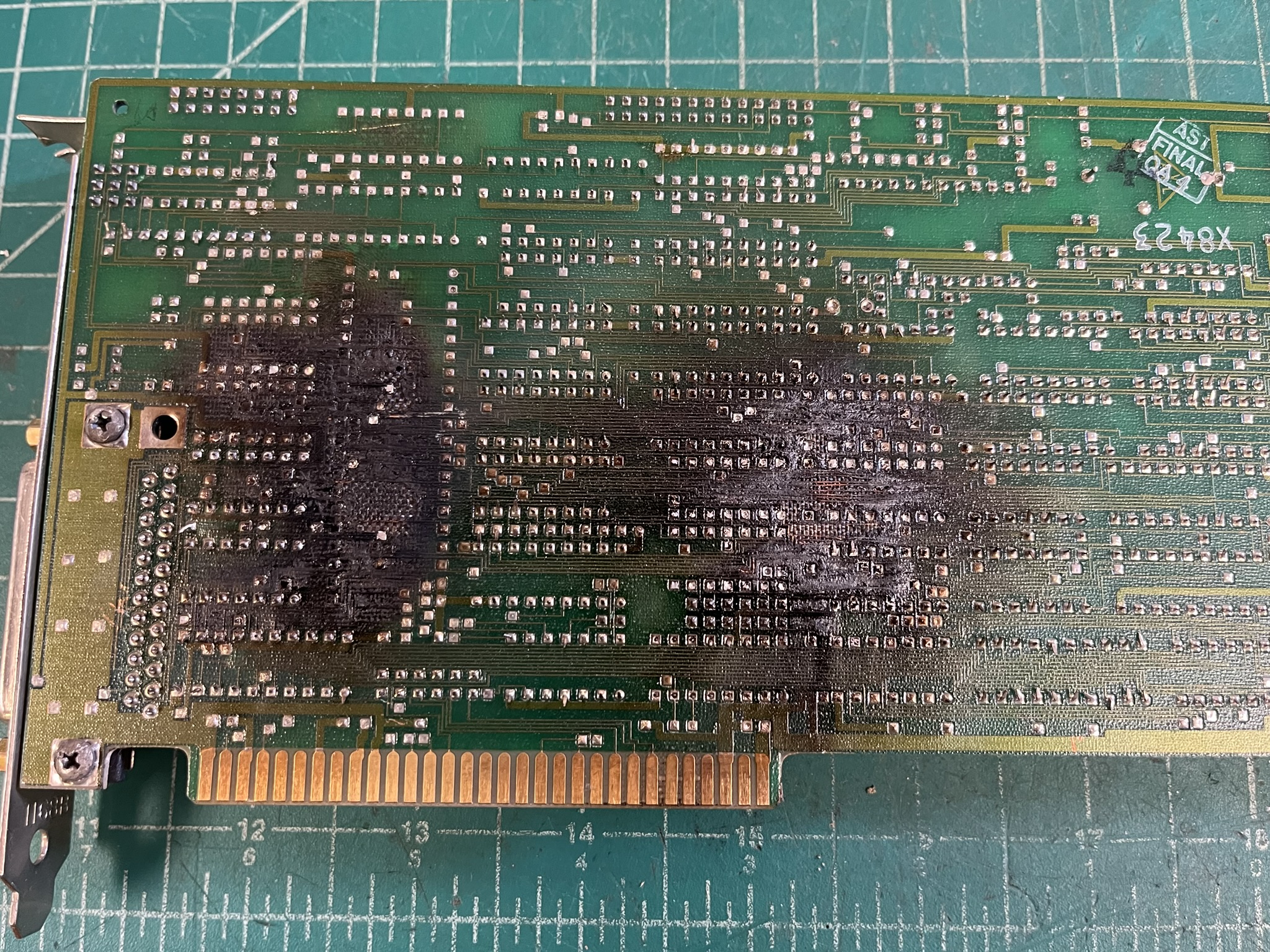
The burn was pretty rough, but was disclosed in the listing, and the price reflected it. I figured, for $10, there were enough parts on the board to make it break-even if it wasn’t repairable – the DRAM and the RTC, mostly. The board was burned badly enough that traces were floating in the air in the charred remains of the solder mask and the upper layers of the FR4 lamination. There was some minor bubbling…hopefully no inner layers were too badly damaged.
The following components had been removed:
- 8250 Asynchronous Communications Element (ACE)
- 1489 RS-232 receiver
- 74ALS04 hex inverter
- 2x 74ALS08 quad 2-input AND gate
- 2x 74S32 quad 2-input OR gate
- 74LS90 counter
- 16-pin DIP socket
- 1N270 germanium diode
- 3x 1N4148 silicon diodes
- 2N2222 transistor
- 5-35 pF variable capacitor
- 3x tantalum capacitors
- 3x 100 nF MLCC ceramic capacitors
- 6x 10 nF film capacitors
- 2x 2.2 nF ceramic capacitors
- 1x 330 pF ceramic capacitor
- 1x 47 pF ceramic capacitor
Quite a bit of scavenging! Curiously, the RAM was still installed, and the switch settings indicated the board had been run with the 128K of RAM that was still present. I’m guessing someone was picking parts for other electronics projects…I did that, growing up, and even used a blowtorch to remove parts, but I generally didn’t set the boards on fire!
We had all of the components for the repair in stock, the first thing was to see if the RAM could be made operational.
RAM Repair and Testing
I started with desoldering a few components that were left crooked by the blowtorch harvesting, retinning pads, and clearing them again with the Hakko 472D vacuum desoldering station. I wanted to check for open through-hole plating by clearing them and adding new solder from the bottom side, then checking to make sure the solder was pulled to the top side. My main concern here was open vias to inner layers. Fortunately, everything pulled solder through.
I then cleaned char from the burned area. This was for two reasons: to remove possible resistive carbon shorts, and to separate the traces that had detached from the FR4. Some of them were clearly touching. The char was gently cleaned with a soft bristle brush and alcohol. The traces were carefully separated with fine tweezers and left floating in the air – I wasn’t doing trace repair at this time, as I wanted to make sure the board wasn’t totally fried before spending time on it.
Next, chips essential to RAM operation were reinstalled. This included all of the 7400 series logic ICs. One of the chips I desoldered due to it having been partially dislodged during the blowtorch harvesting was U78, a Signetics 82S129 bipolar fuse PROM. I also desoldered U84, a Signetics 82S137 fuse PROM. Both were socketed, and the fuse PROMs were dumped in the Data I/O 29B with UniPak 2B. The ROM dumps, in Intel HEX format, are available here:
- U78, 82S129, marked
1169U78_1169.HEX - U84, 82S137, marked
1183U84_1183.HEX
Now we’re ready for initial testing. I populated the rest of the RAM area and set the SixPakPlus DIP switches for 384 KB starting at 256 KB (0x040000). I then set up a spare Type 2 IBM 5150 PC motherboard with 256 KB onboard RAM on the test bench:
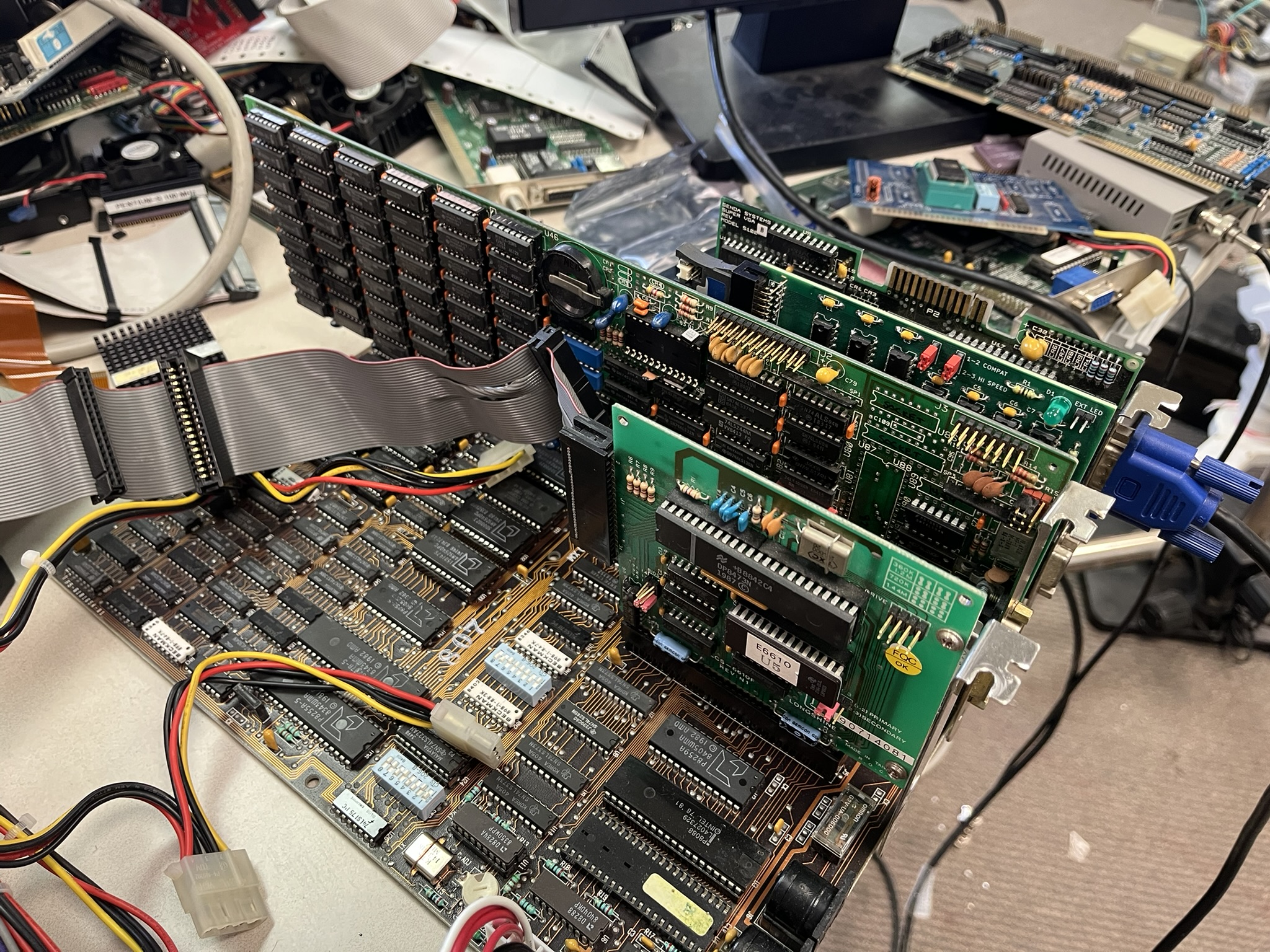
…excuse the test bench mess! The POST caught a bad DRAM (Micron, shocking!), and the Check-It 2 program buffers test caught another in the 0x060000 to 0x06FFFF range. After replacing the faulty DRAMs, I ran Check-It 2’s memory test in non-quick mode, for three passes:
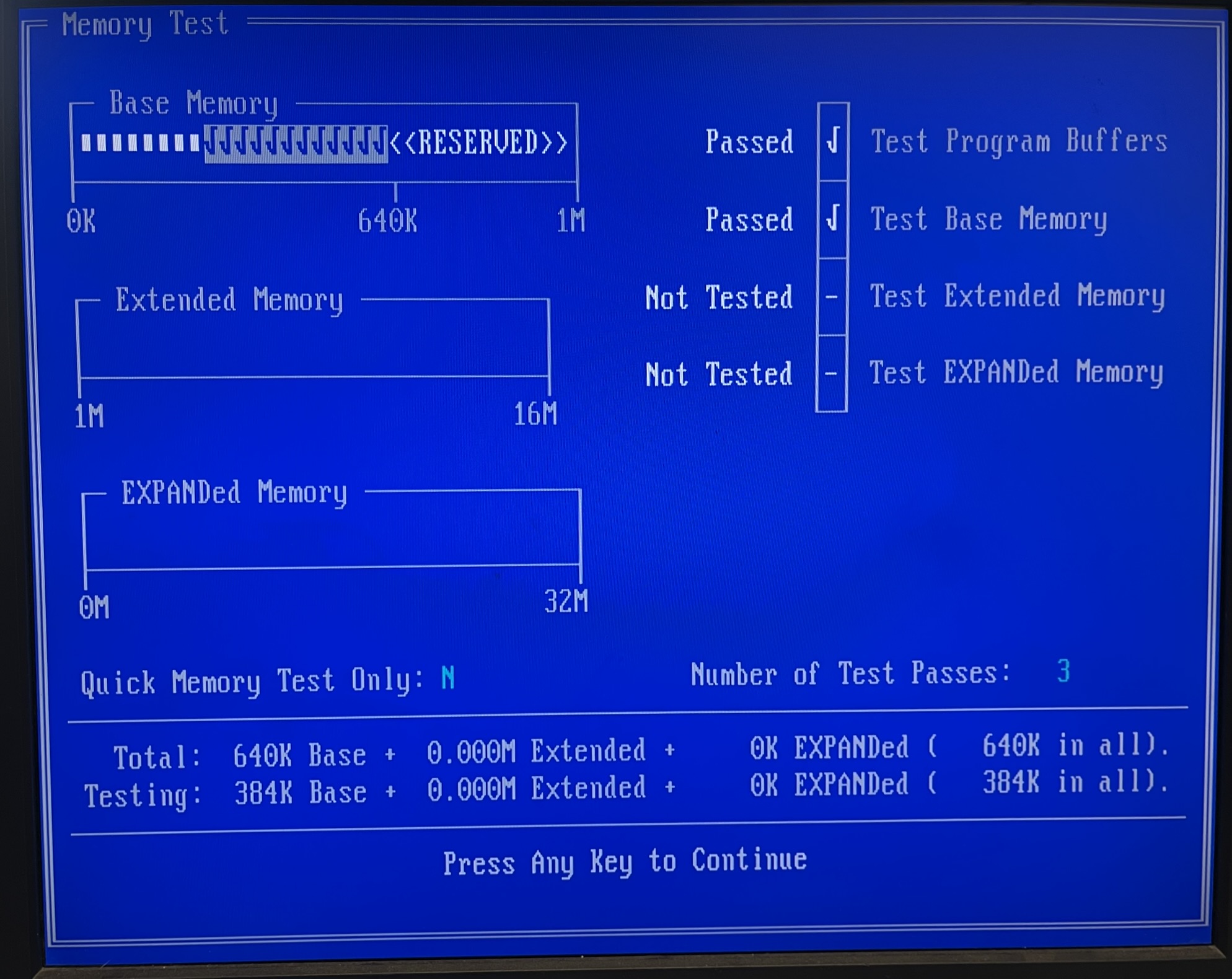
Good progress! Now on to the rest of the board…
I/O Repair and Testing
With RAM working, the board was worthwhile to fully repair. I started with the serial port, since it was a known quantity and should be easy to test with a loopback plug. The 8250 ACE and 1488/1489 RS-232 interface ICs were socketed – the ACE because of the extensive damage around its footprint, and the 1488/1489s because they’re a common failure item on any RS-232 interface, and this poor SixPakPlus wasn’t going to hold up to much reworking after this!
RS-232 testing was conducted with Check-It 2 as well, and a loopback plug from my Landmark KickStart 2 test kit. All tests passed!
The parallel port was the next consideration, since it was only missing passives. I was going to test with Check-It 2, but apparently my Landmark parallel loopback plug isn’t compatible. What could I test with that would really exercise the parallel port? How about a Xircom Pocket Ethernet adapter:
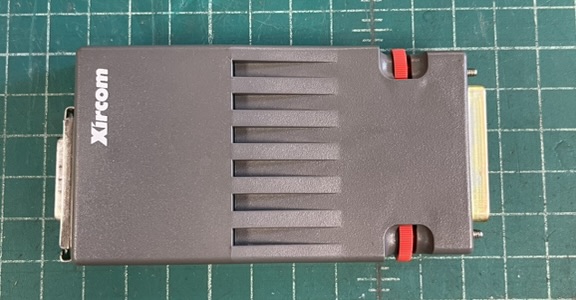
The above is the original Xircom Pocket Ethernet, not one of the more common PE2 or PE3 adapters. It features an AUI port for its Ethernet connection, and must be used with an external transceiver. It seemed like it should be a pretty good test for the parallel port, as it would run it fast and use all of the available lines. I installed the packet driver from the original 3.5” DSDD 720K installation media (ImageDisk file here if you need it). The industrial Flash module installed in the test system’s XT-IDE already contained an install of Mike Brutman’s excellent mTCP TCP/IP applications. The packet driver found the Pocket Ethernet, configured it, and printed its MAC address. I used mTCP’s IRCjr to connect to irc.slashnet.org and joined #vc, the vintage computer channel. Success!
Now for the real-time clock. Several components had been stolen from this area, including four diodes and the trimmer capacitor for the RTC oscillator. The circuit seemed to differ from the example in the MM58167AN datasheet. Fortunately, AST included schematics in the manual, which you can find on minuszerodegrees.net – this card is a first revision SixPakPlus and the corresponding manual is from June 1983.
The only somewhat oddball part was the 1N270 germanium diode, needed for its low voltage drop. We actually stock these because they’re often cracked on TDL SMB S-100 boards. I used a version of ASTCLOCK.COM with this Y2K patch to set the time, powered the system off for 15 minutes, and restarted. The clock retained the correct time! The trimmer capacitor will probably require adjusting to get the RTC to keep accurate long-term time.
This leaves one final item: the game port. This board didn’t come with the optional ICs for the game port, and I don’t have them handy at the moment, so it won’t get tested now. I did install the 10 nF film capacitors for it.
Permanent Board Repair
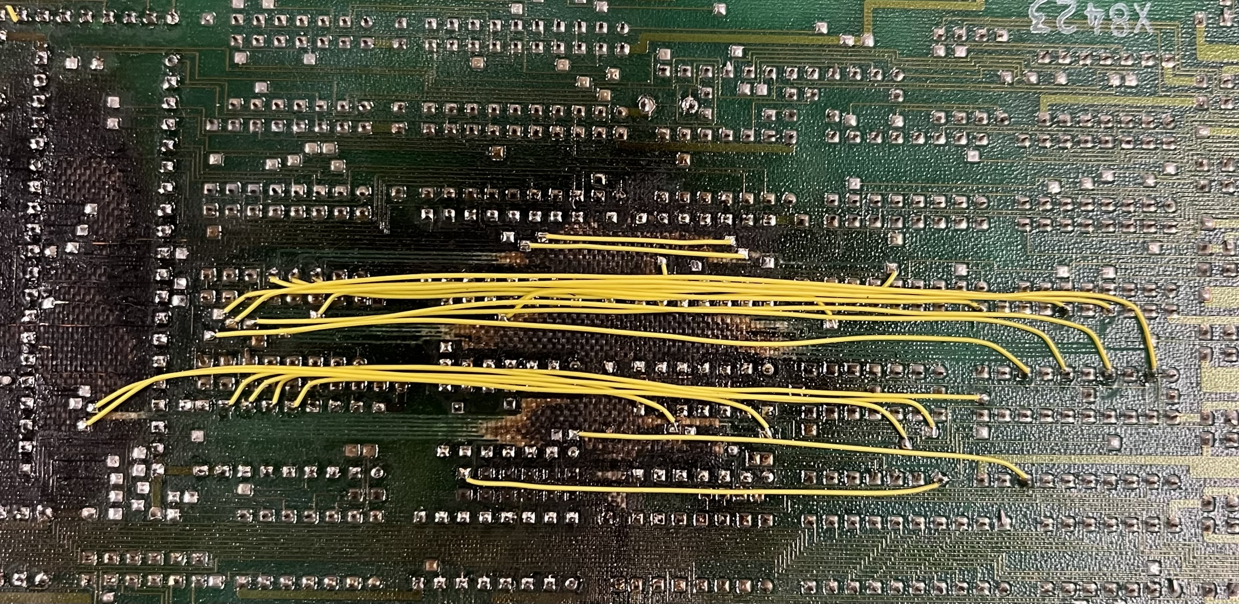
The above work was just to make sure everything was actually working before making board repair/rework permanent. Obviously, delaminated traces floating in the air weren’t going to hold up long-term. My usual solution is to cut the traces back to their next-closest pad or via, and install 30 AWG Kynar flywires.
The process is pretty simple: I typically start in the middle of the trace, gently lifting it up and peeling it from the board using fine tweezers without knurling. Once I have it lifted, I confirm I have the right end pads with the bench meter in continuity mode. Then, one end’s pad gets tinned with fresh solder, and the stripped end of a piece of Kynar wire is soldered down. The Kynar wire gets routed, marked for the point at which it should be stripped, cut about 1/2 inch long, stripped, and soldered down. The extra bare wire allows one to hold it with tweezers and get it just where it needs to be, then the excess is trimmed off. Once the Kynar repair wire is in place, the other end of the lifted trace is cut. This method minimizes the chance of mistakes. Here’s the results:
The board was then thoroughly tested again, including an overnight run of Check-It 2’s memory tests. Everything passed, so the board was washed and dried in the hot air drying cabinet. The flywires could now be staked down with epoxy and made permanent:
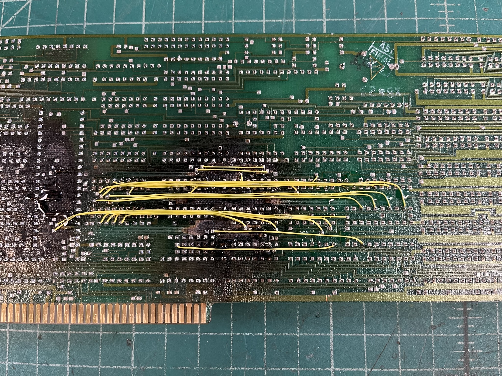
I also covered some of the traces in the charred area which had not come free from the FR4 and were in acceptable condition. This will prevent their future lifting. Here’s the completed repair, front and back:
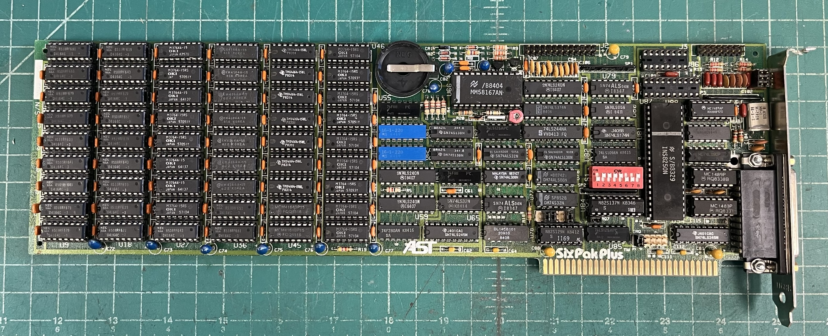
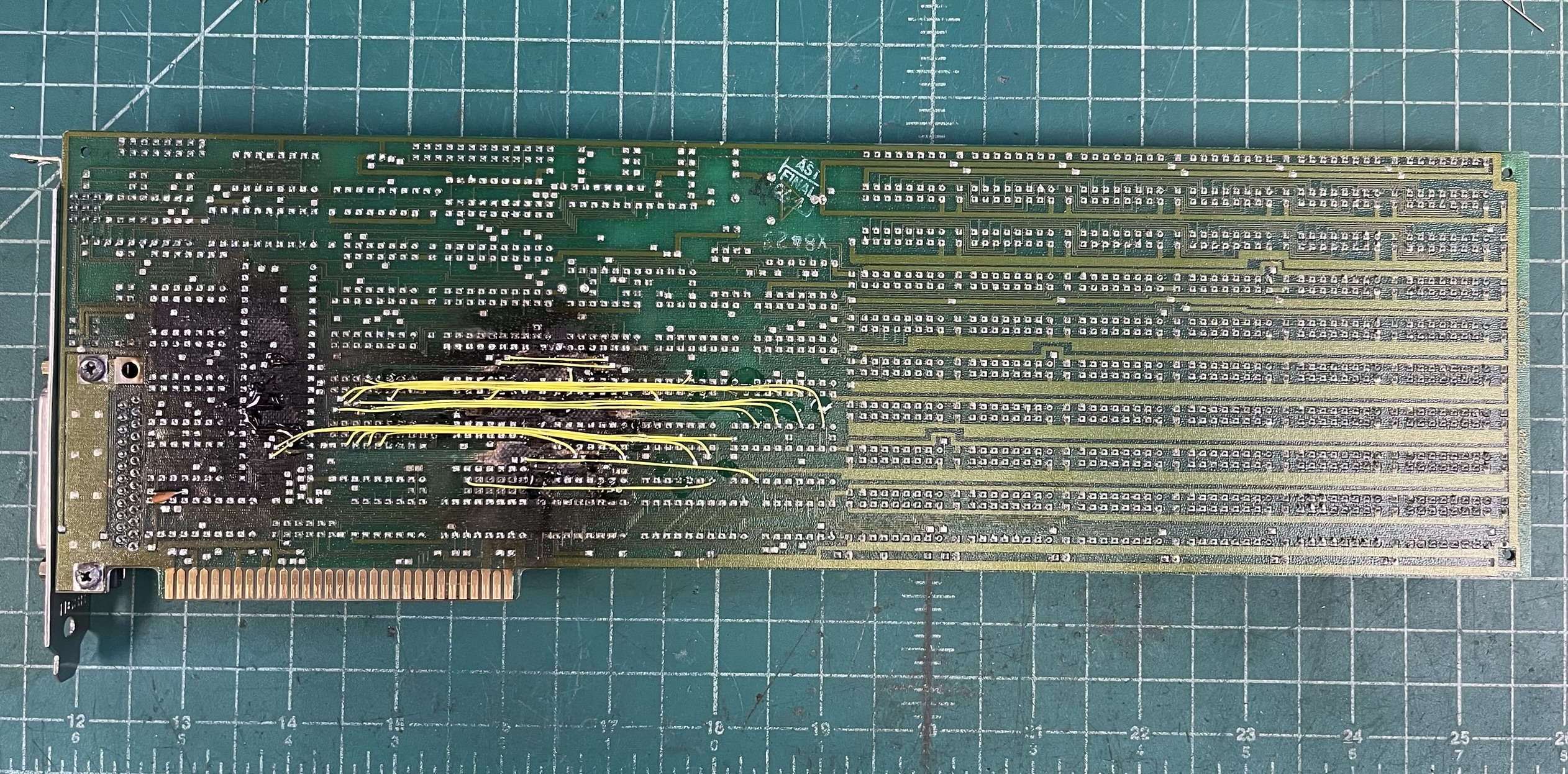
I think it turned out pretty good, considering what we started with!
Conclusion
So, there you have it, “how to get a cheap AST SixPakPlus in 2026!” What did I want this board for? Well, aside from the challenge, it is being used to test 4164 type DRAMs, both for our inventory and for finding dead RAM in systems that aren’t operational enough to test their own RAM. The older SixPakPlus boards which use all 4164 DRAMs are ideal for this: when plugged into a system board with 256KB RAM, the test system can still come up even if some of the RAM on the SixPakPlus is dead. Additionally, locating a RAM chip detected as bad is easy: the columns of DRAMs start at 0x040000 on the end closest to the bracket, and bit 0 is at the bottom. You also get to test 54 DRAMs at once!
Why test like this? It provides a better at-speed test using known and trusted tools, rather than some of the bit-bang testers powered by a modern microcontroller. There seems to be no substitute for testing at speed, as I’ve had several folks send in systems in which they assured me all RAM was good, having been tested in some modern hobbyist-targeted chip tester…only to find out that there’s still a bad RAM in there.
charred boards made operational