Topic: YES-100 cleanup, repair, reverse engineering
Date: 2024 MAR 25
The Yang Electronic Systems, INC. S-100 Memory, or YES-100, is a 32K static RAM board for the S-100 bus. Like many boards from smaller manufacturers of the era, there is little information on this board on the Internet. It appears to be something produced by YES for their YES-5 single-board computer, though it can be jumpered for standard S-100 compatibility. It supports battery backup, as did many 6116-based SRAM boards of the era; however, it includes the battery onboard, which of course opens the possibility for corrosion:
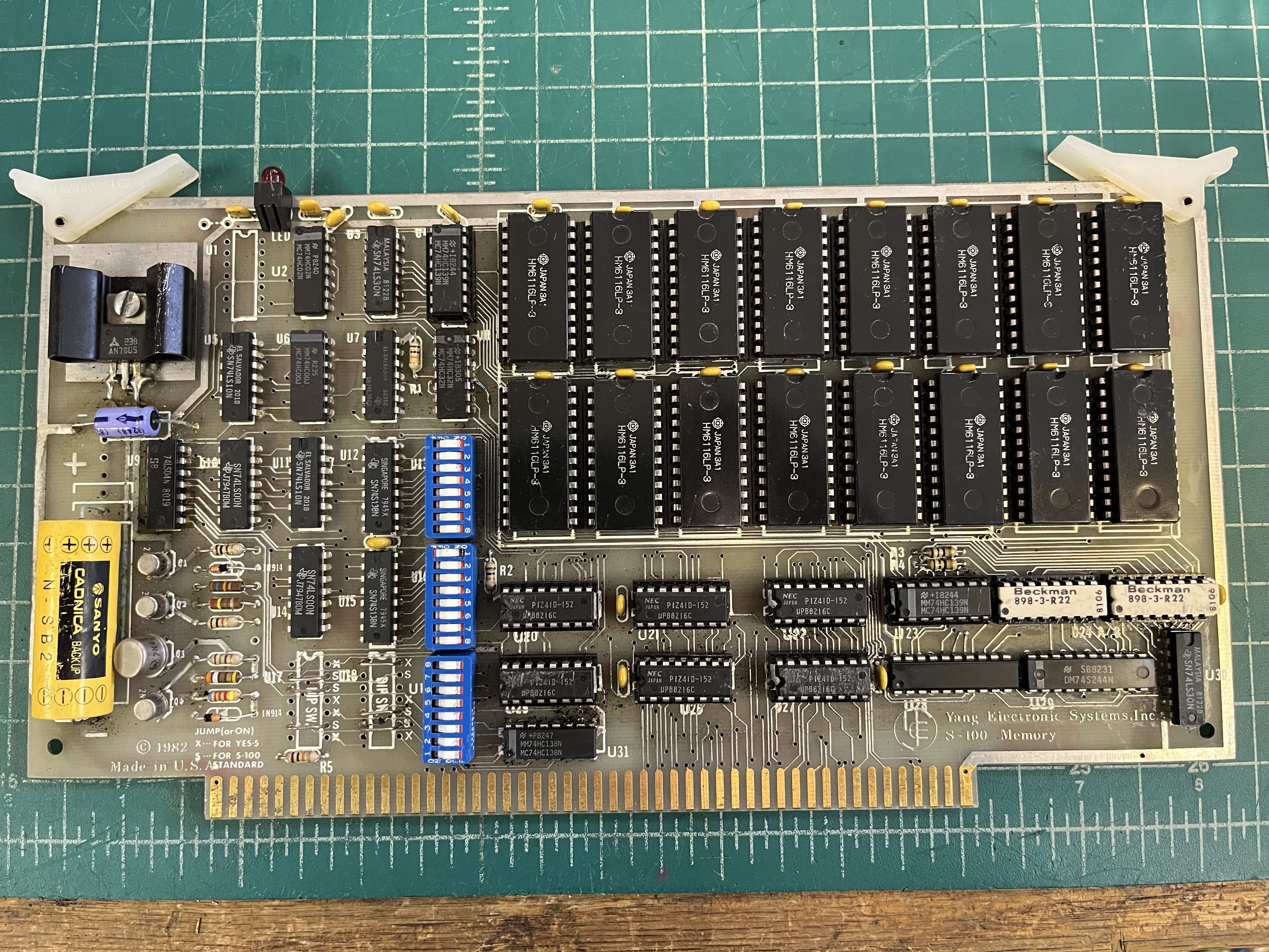
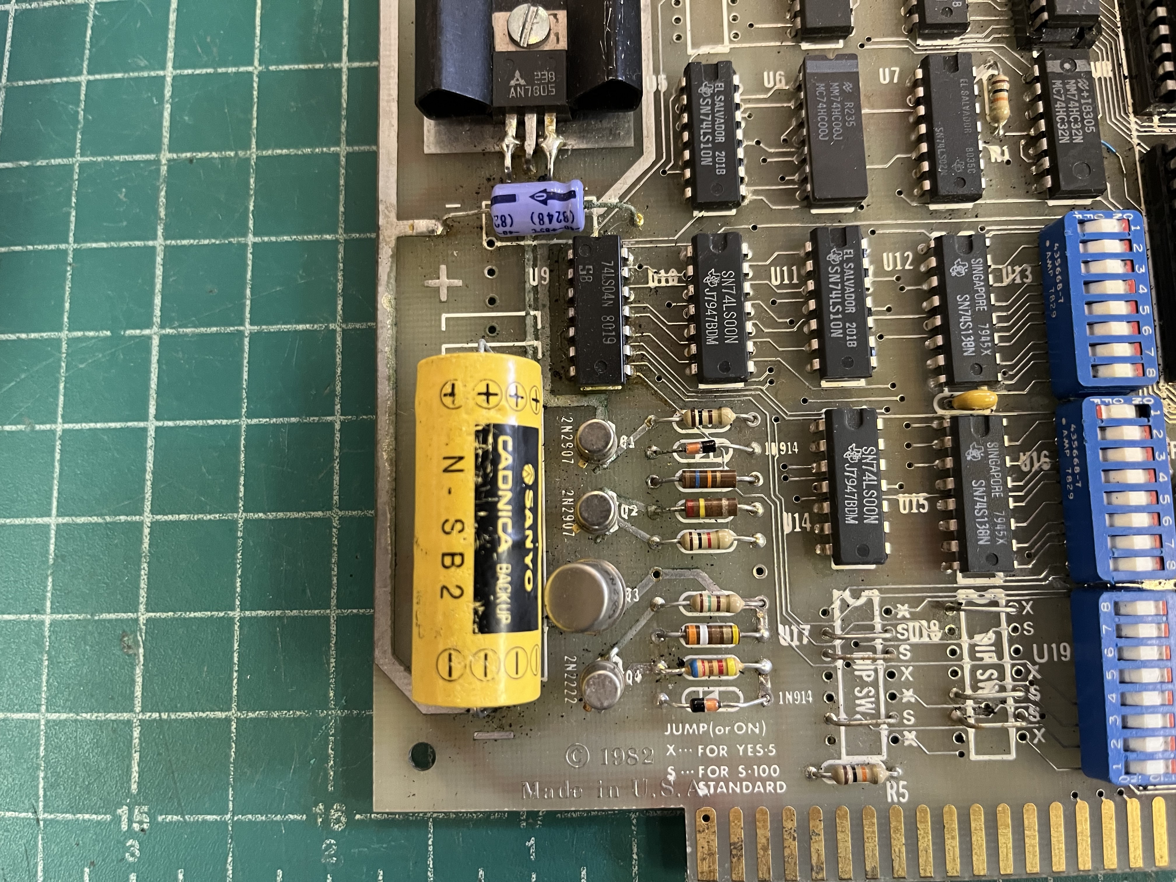
This YES-100 came in a larger lot of S-100 equipment, and the battery had indeed leaked, as seen above. The battery was a Sanyo nickel-cadmium rechargeable, and fortunately had not leaked that badly. The battery was removed, along with several components, the corrosion cleaned up with Superior #30 flux, and components reinstalled. In the process, the 47 uF electrolytic capacitor was replaced, and the 5V regulator was replaced. The original 5V regulator had a capacitor soldered across the input and output terminals…it was not really clear why this was done. The new regulator was installed with two ceramic 0.1uF capacitors added to the back side of the board.
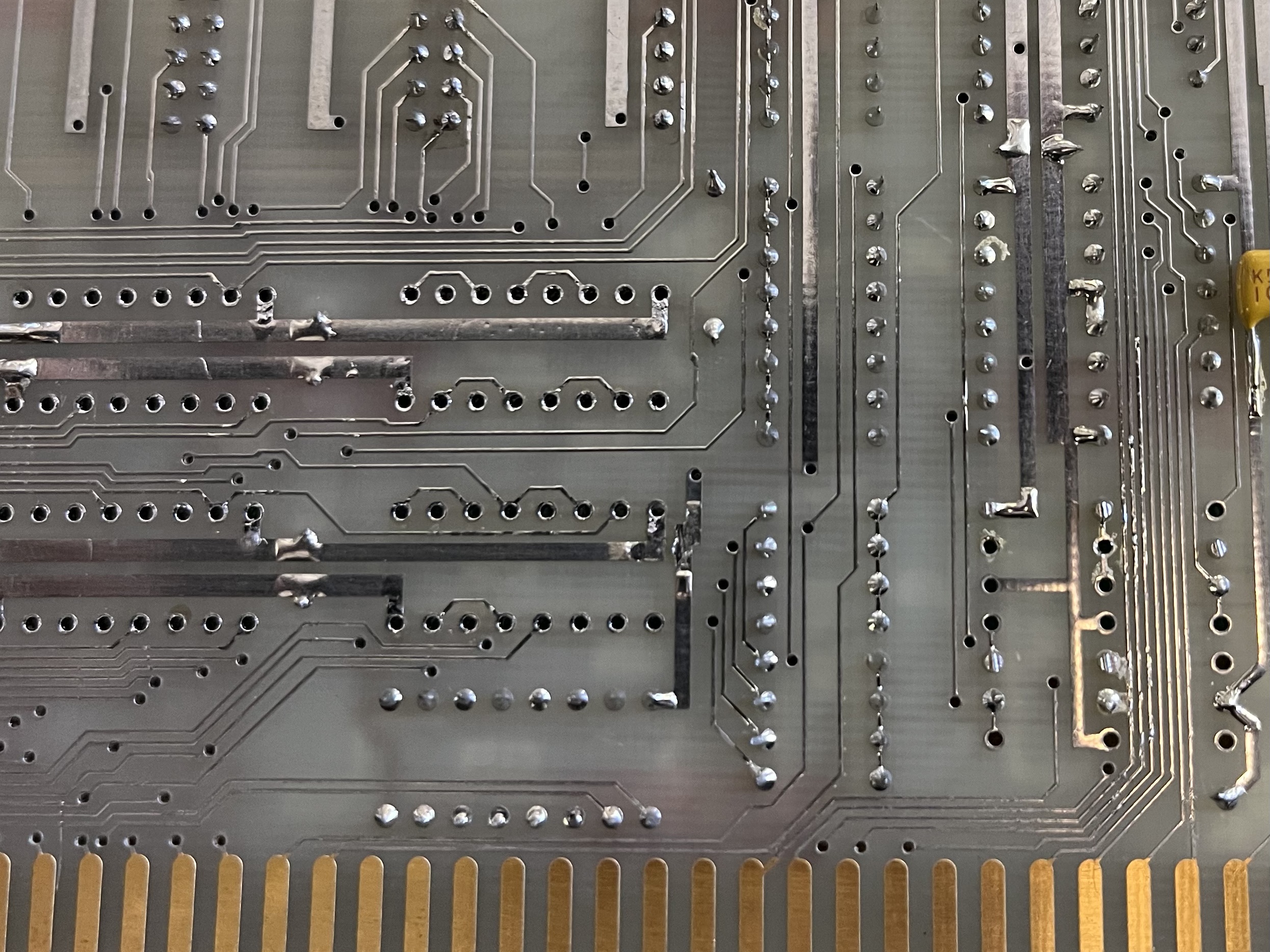
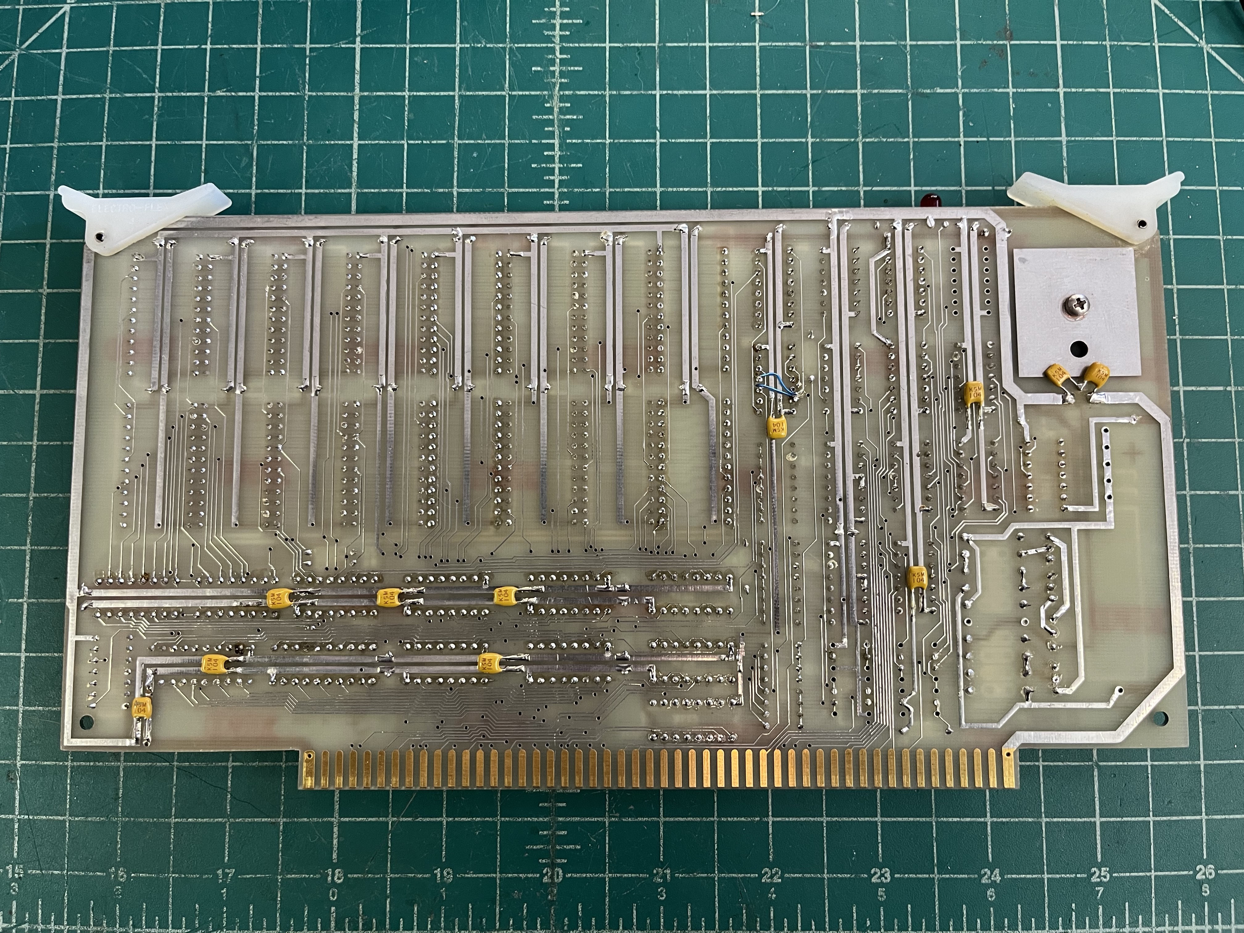
This YES-100 appears to be a prototype or early revision: there are bodge wires, cut traces, etc. and it lacks the solder mask of other examples found on the Internet. There’s a cut separating the +5V VCC rail from the battery-backed VCC rail, near U11 on the back:
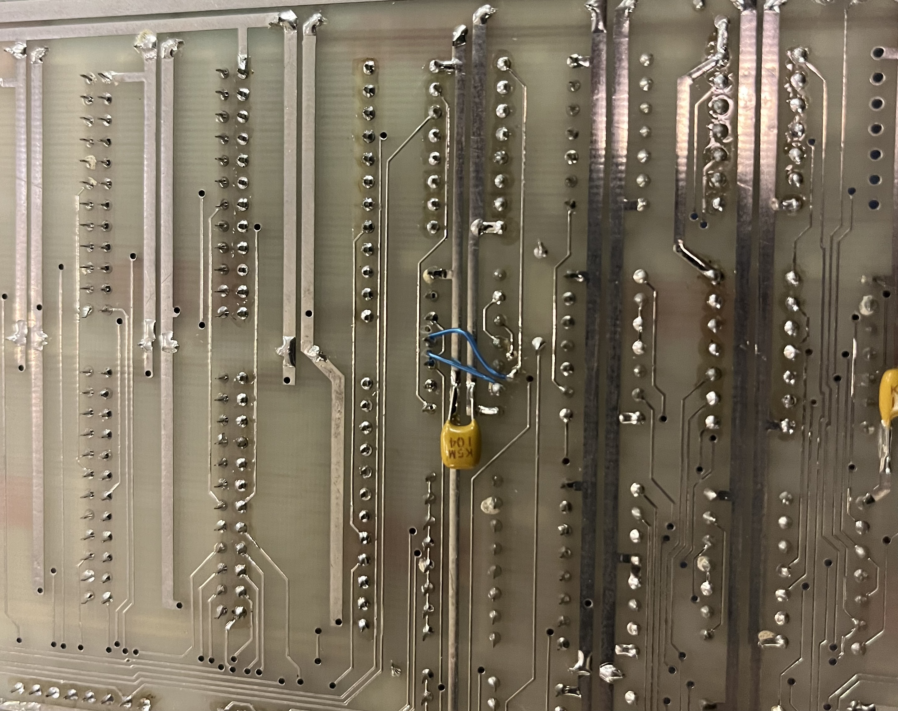
This cut had a 0.1uF ceramic capacitor installed across it. I’m not sure why someone chose to install a capacitor like that! There were many capacitors added to the back of the board, which appear to be top-side on later revisions. There were two dropped traces fixed with flywires near the 74HC244, and this repair around a 74HC32:
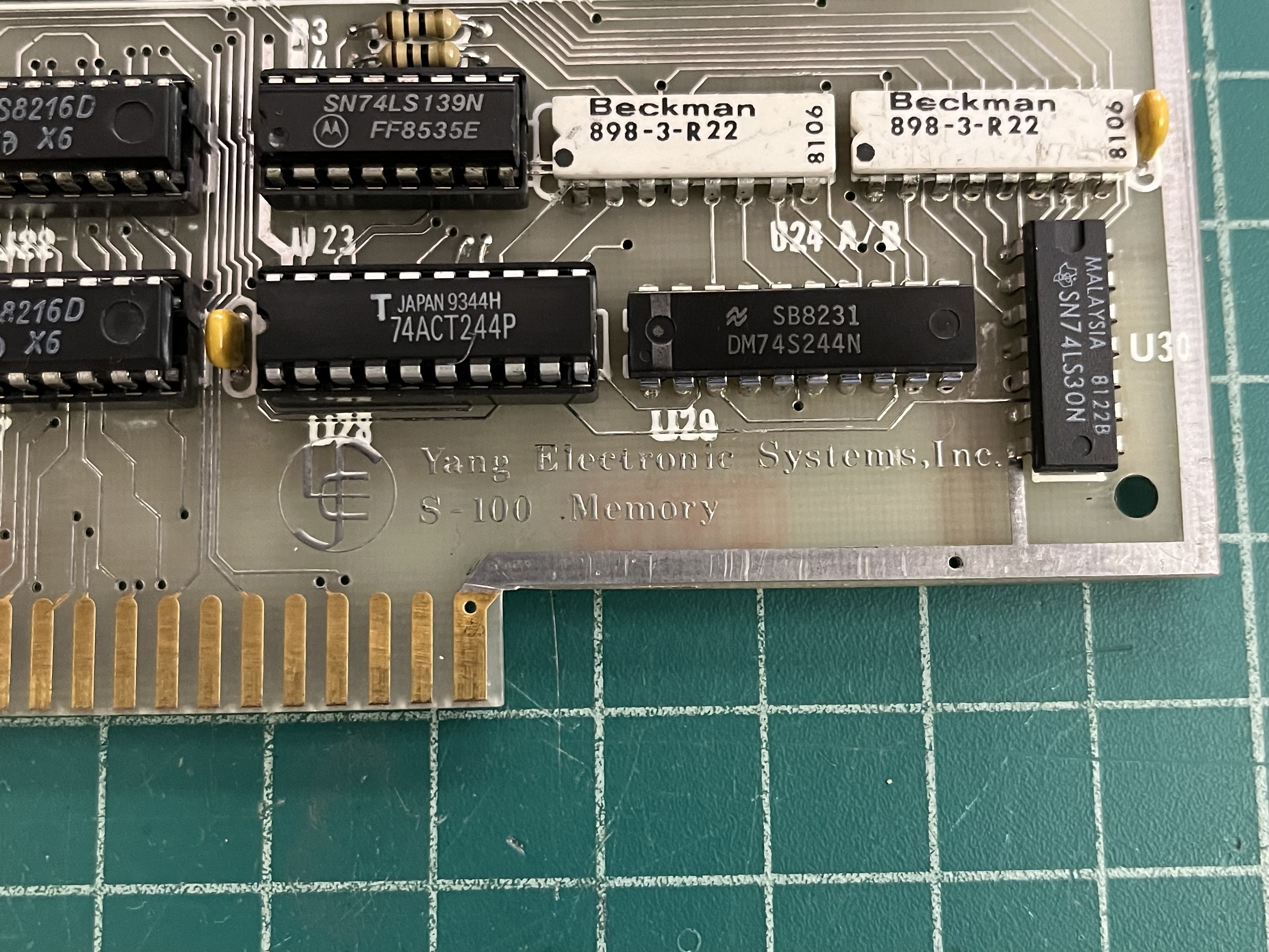
This board also has a different designation to the other YES-100 I’ve found online:
Board Design and Addressing
The board’s design is pretty weird for 1982: it uses 6116-type 2K x 8 static RAM chips, but also 8216 bidirectional bus buffers, which are an old mid-1970s Intel design. It supports extended addressing, but only 22-bit, not the full 24-bit of the IEEE-696 standard. 16-bit support is also included, but was not tested during debugging.
Battery backup was implemented in an odd fashion: there are two VCC rails, one +5V rail, and one +3.6V rail. I don’t have manuals for this board, so I can’t be sure, but it seems that 74HC series CMOS ICs were used in several positions so that they can remain powered up when the YES-100 is operating on battery power. These chips, along with the 6116s, receive a VCC of 3.6V even when the board is operating on system power! There’s a jumper spot above U1 and to the left of the activity LED for connecting these two rails and just powering everything off +5V. I chose to do this, and replaced the 74HC parts with TTL-compatible parts.
The YES-100 is organized as two 16K banks, separately addressable on 16K boundaries within a single 64K segment of memory. The board uses a split odd/even byte layout, with the odd byte being the top row, and the even byte being the bottom row. This pretty well precludes the use of 2716-type EPROMs, unless one wants to split an image across two ROMs and use 4K of memory space. The switch settings are a little odd:
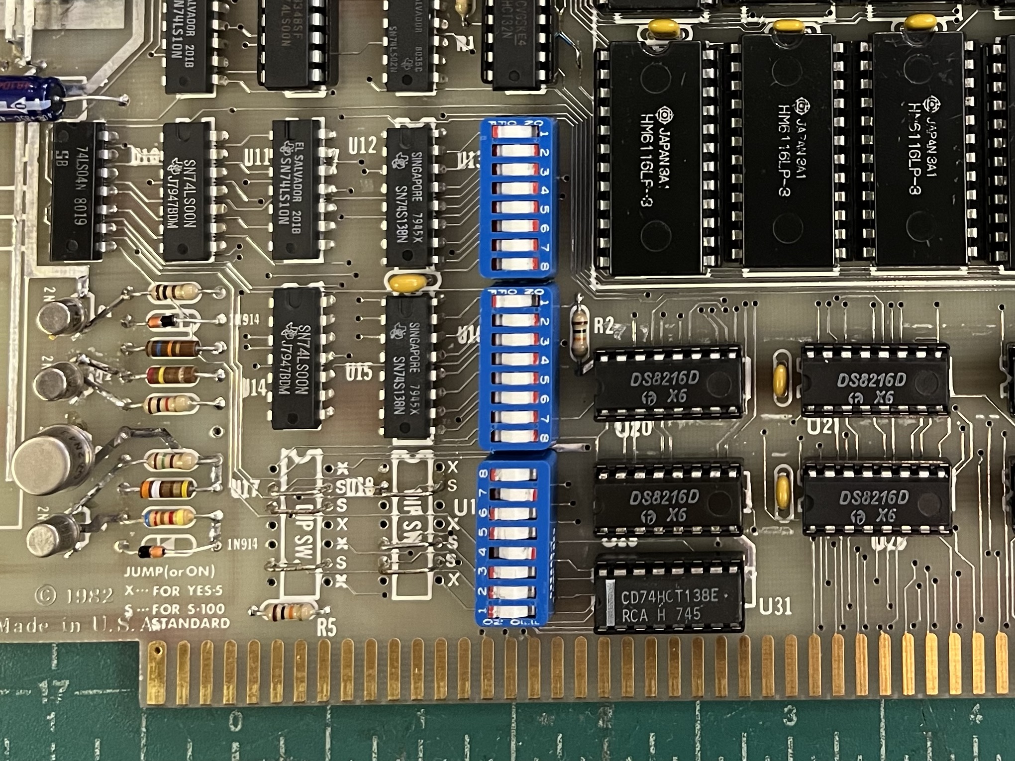
The above settings place the YES-100 in the bottom 64K segment of memory, at 0x0000 through0x7FFF. Switch U13 is connected to the outputs of U12, which decodes extended address lines A16, A17, and A18. Switch U16 is connected to the outputs of U15, which decodes extended address lines A19, A20, and A21. Extended address lines A22 and A23 are ignored.
To select the 64K segment in which the YES-100’s memory will be located, close the switch corresponding to the segment. U13 switch 1 corresponds to A16, A17, and A18 low, switch 8 corresponds to all high. Likewise, U16 switch 1 corresponds to A19, A20, and A21 low, and switch 8 corresponds to all high. Only one switch in each switchpack may be closed, as the outputs of the 74S138 decoders will fight otherwise. I’m not sure why this addressing scheme was chosen.
Switch U19 selects the 16K boundary for the start of the two 16K blocks of RAM. Note that U19 is installed upside-down from U13 and U16 on my board – I don’t know if this is intentional. U19 is electrically divided into two sections, consisting of positions 1 through 4 for one section, and positions 5 through 8 for the second section. Only one switch in each section may be closed. Positions 4 and 8 correspond to 0x0000 starting address, positions 7 and 3 correspond to 0x4000, and so on.
U17 and U18 may be switches or wire jumpers. On my YES-100, and on the other YES-100 I’ve found pictures of online, they are wire jumpers. Short the positions marked S for use in standard S-100 systems. Positions marked X are for compatibility with the YES-5 board.
Final Repairs and Testing
I found several bad sockets in my YES-100, these were detected during runs of the Rasmussen memory test at 2 MHz. In an attempt to get the board stable at 4 MHz, I ended up replacing the sockets of several logic ICs, which did not help. I still get random failures at 4 MHz with my Cromemco ZPU board. I’m not sure why, perhaps this board just isn’t a stable design for 4 MHz operation.
The 8216 type bidirectional buffers that came with this board ran extremely hot, and were replaced with later manufacture parts that run much cooler. Speaking of heat, the 7805 regulator could probably use a bigger heatsink – it runs quite warm in the IMSAI, though it is not dangerously hot, or close to shutdown.
Here’s the board in its finished state:
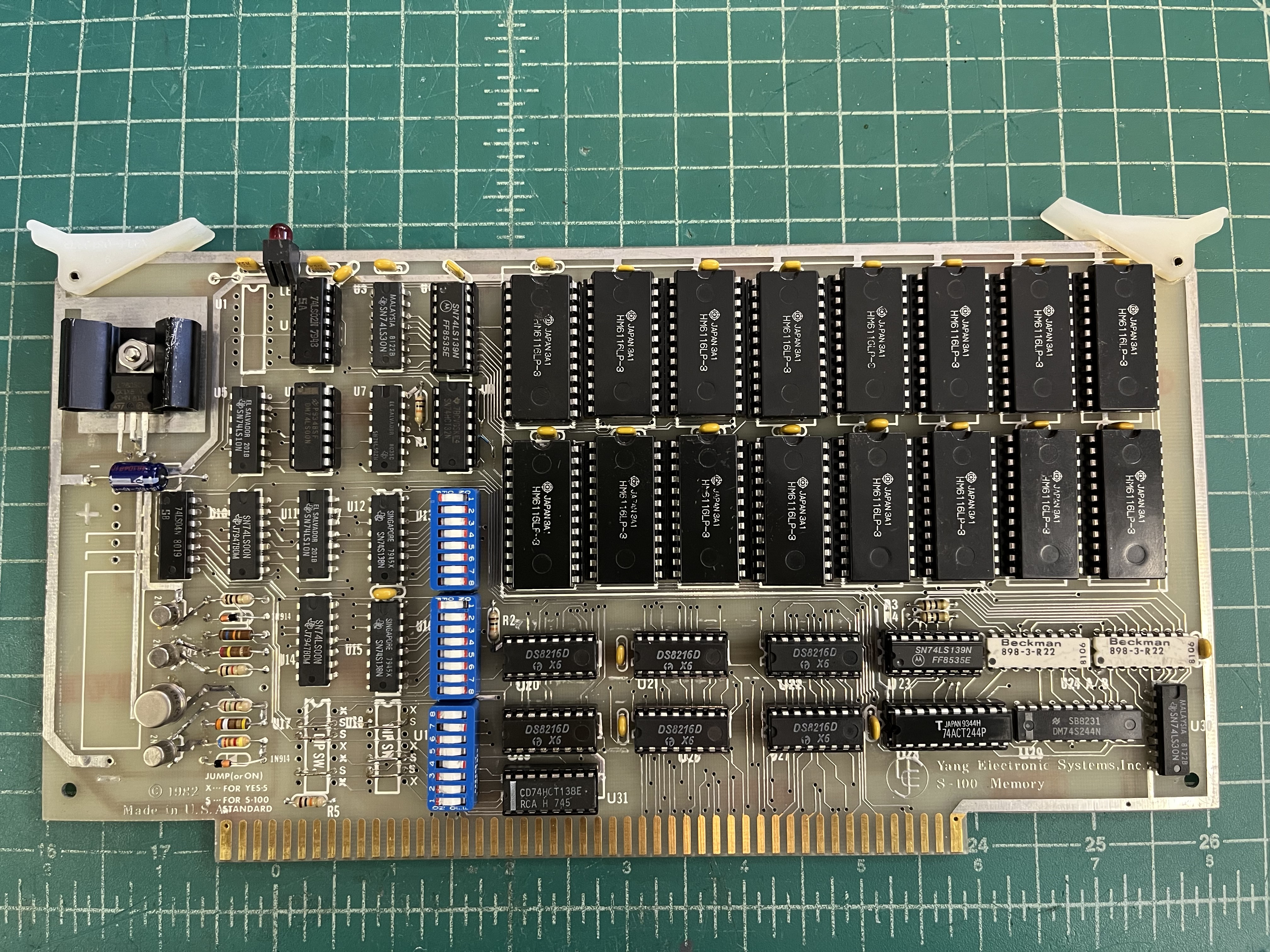
Kind of a strange board design for 1982, but it does seem to work with a 2 MHz 8080! The board draws around 3/4A, so it’d make a decent memory option for a system with a smaller power supply, like an Altair 8800 or Poly-88.
battery messes repaired