Topic: Cleaning up a Gralex Panaplex meter
Date: 2023 FEB 18
I picked up a pair of heavily damaged BAFCO frequency response analyzers at the surplus auction in 2019, along with other damaged “for parts” lab equipment. The interesting characteristic of the BAFCO units was the inclusion of two (per unit) Panaplex displays. These are basically flattened (planar) 7-segment Nixie tubes, and use neon gas discharge to light the digits. I went through one of the meters in April 2020, but apparently never did a writeup on it!
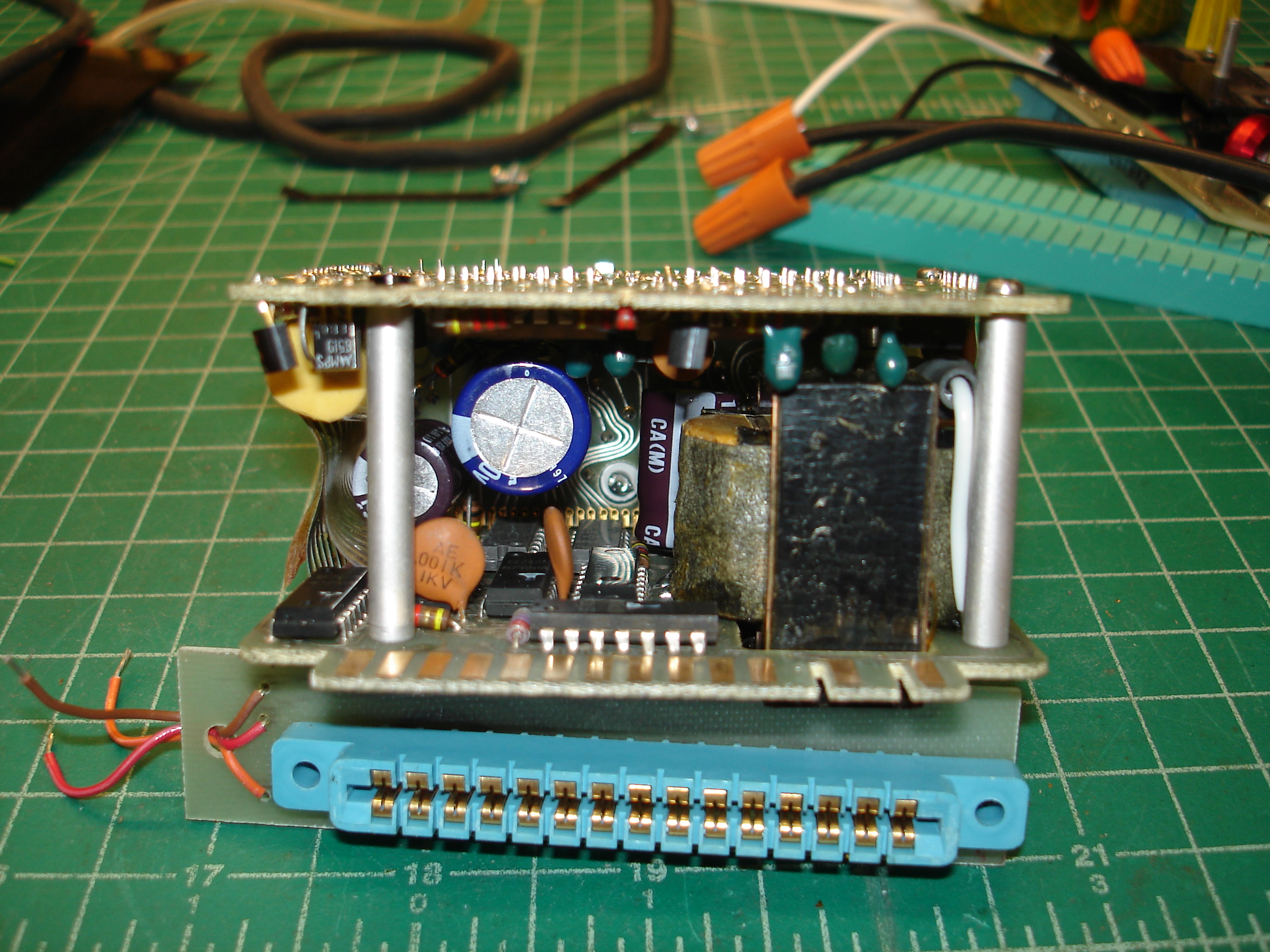
The Panaplex displays turned out to be installed in a pair of Gralex 1500 mV panel meters. The model numbers are likely specific to these BAFCO units. The panel meters were held to the front panel by a U-shaped piece of aluminum, secured to the back of the meters with two truss head screws. They were easy to remove, and since the equipment was being scrapped for parts, I cut the wiring and removed the connector boards, too:
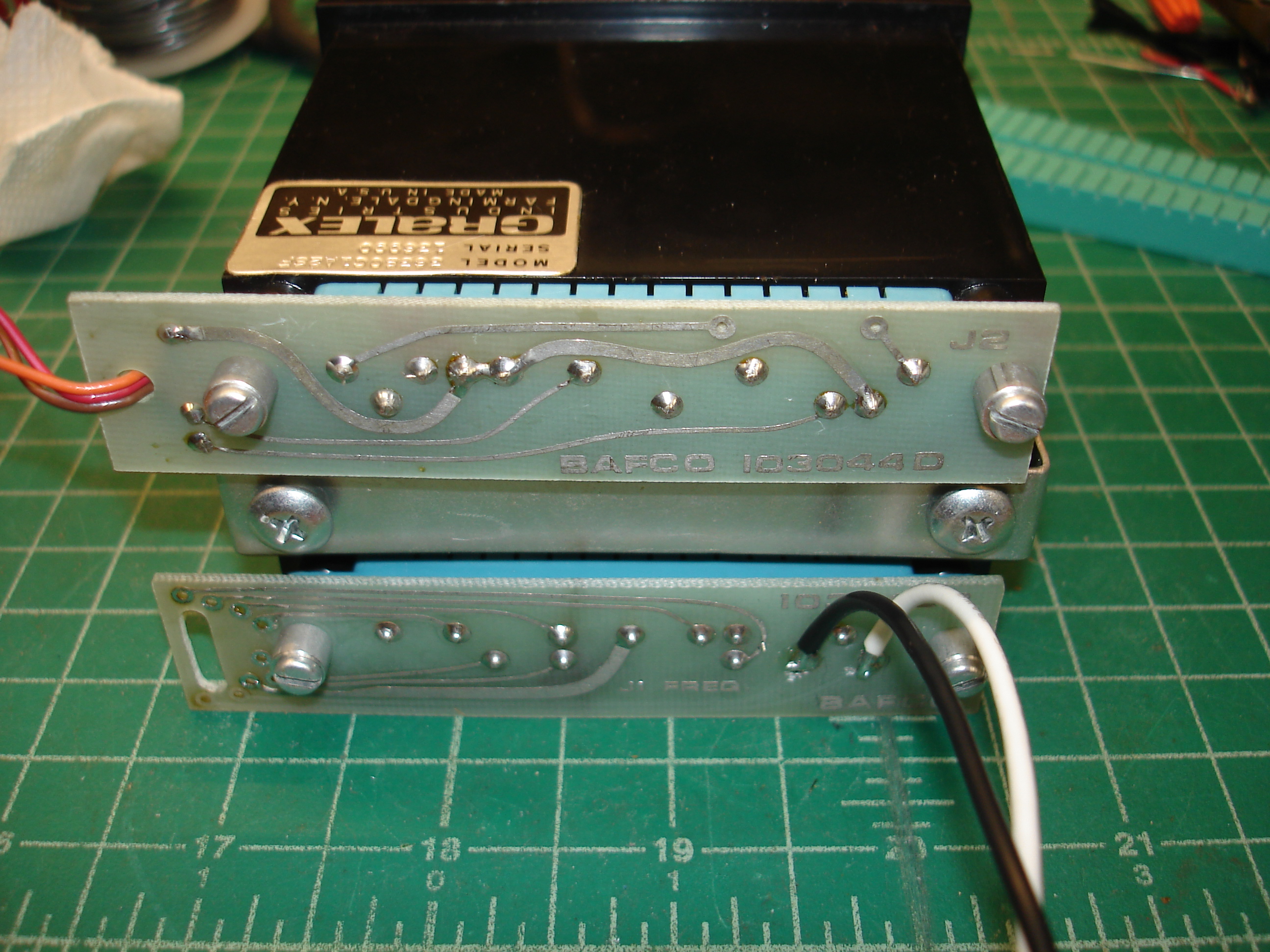
The top connector brings in the signal to be measured, and the bottom connector contains the AC wiring. There are of course other pins present, for things like setting decimal point position. As seen above, I traced out the 120V AC input wiring, cut the traces back, and soldered short wires directly where they were needed. This limits the amount of exposed 120V AC on the bench.
The meters disassemble easily: remove two black metal spring clips on the short sides, and the color filter drops out. Behind that, the displays are visible:
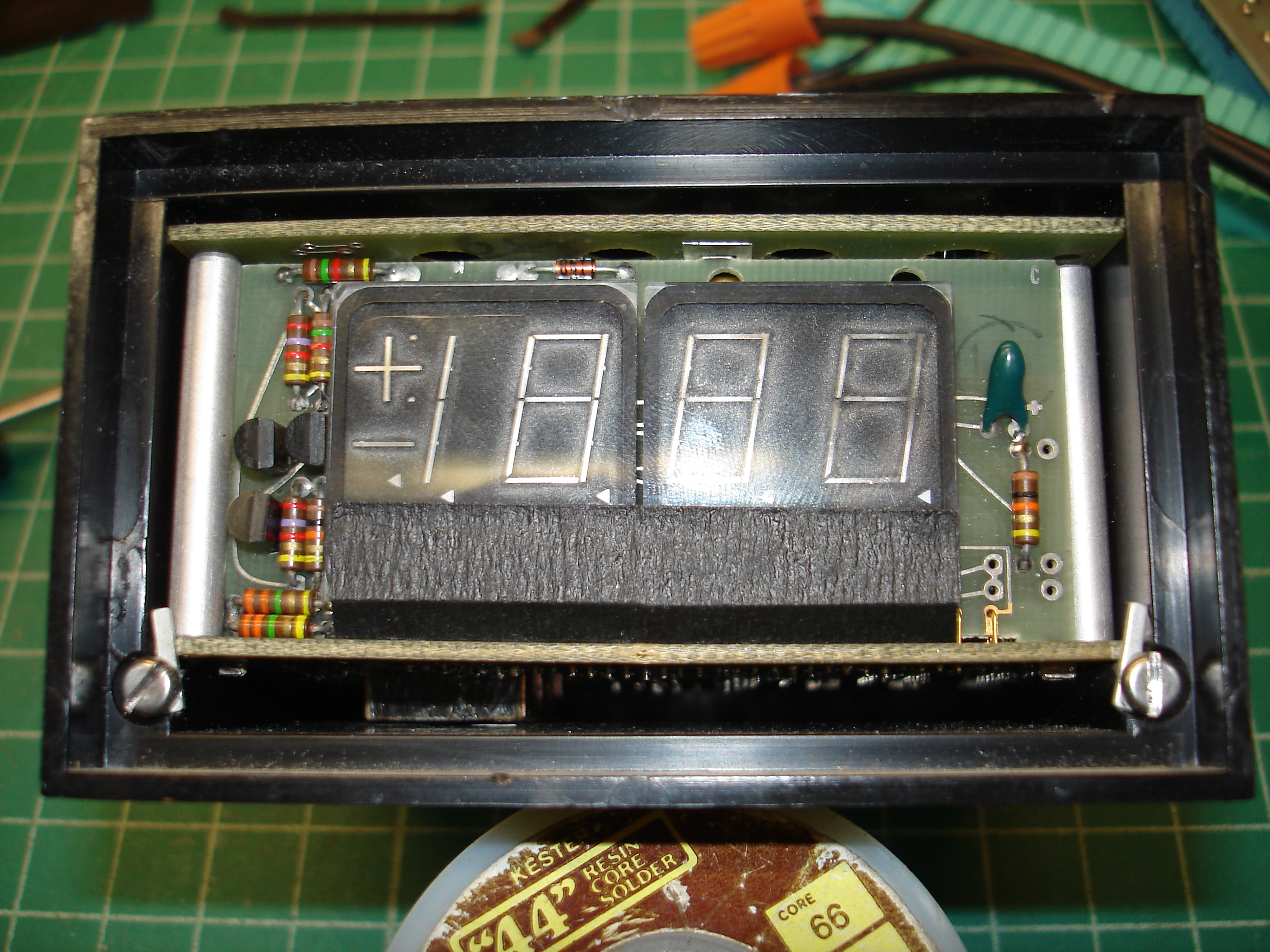
Also visible are the little brackets that secure the circuit boards in the plastic housing. To remove the boards, disconnect the card edge connectors in the back, remove the two screws and P-shaped retaining stampings, and push the whole unit out by the card edges in the back:
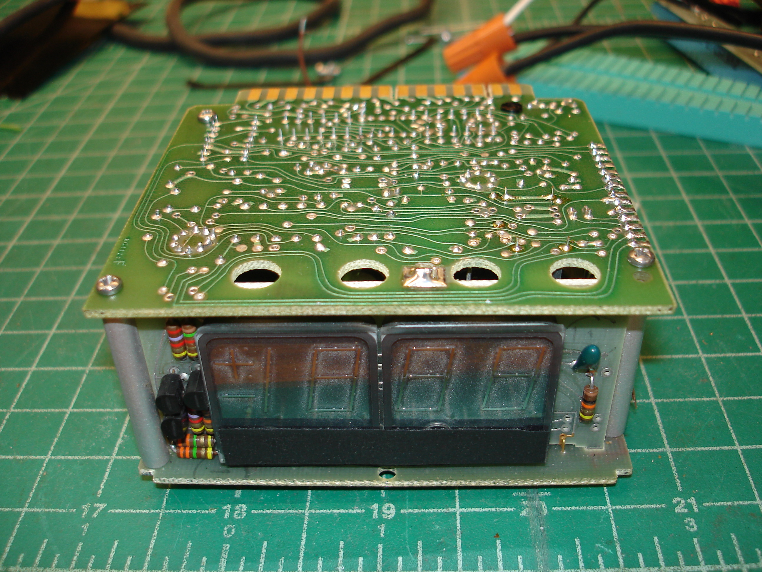
The board holding the displays has a small tab that goes through the top circuit board and is soldered in. This must be desoldered to separate the two halves. Remove the four screws securing the top board to the standoffs that go between the top and bottom boards. The assembly then splits in half, with a flex circuit joining the two halves:

Pretty typical little panel meter! I don’t have a manual or schematic for this particular panel meter, but it’s very similar to the others I’ve worked on, from various manufacturers. The large yellow film capacitor on the top board (board on the right, in the picture above) is the integrating capacitor.
The circuit board with the displays connects to the bottom board using one of my favorite board-to-board interconnects, Components Corp Digi-Klips:
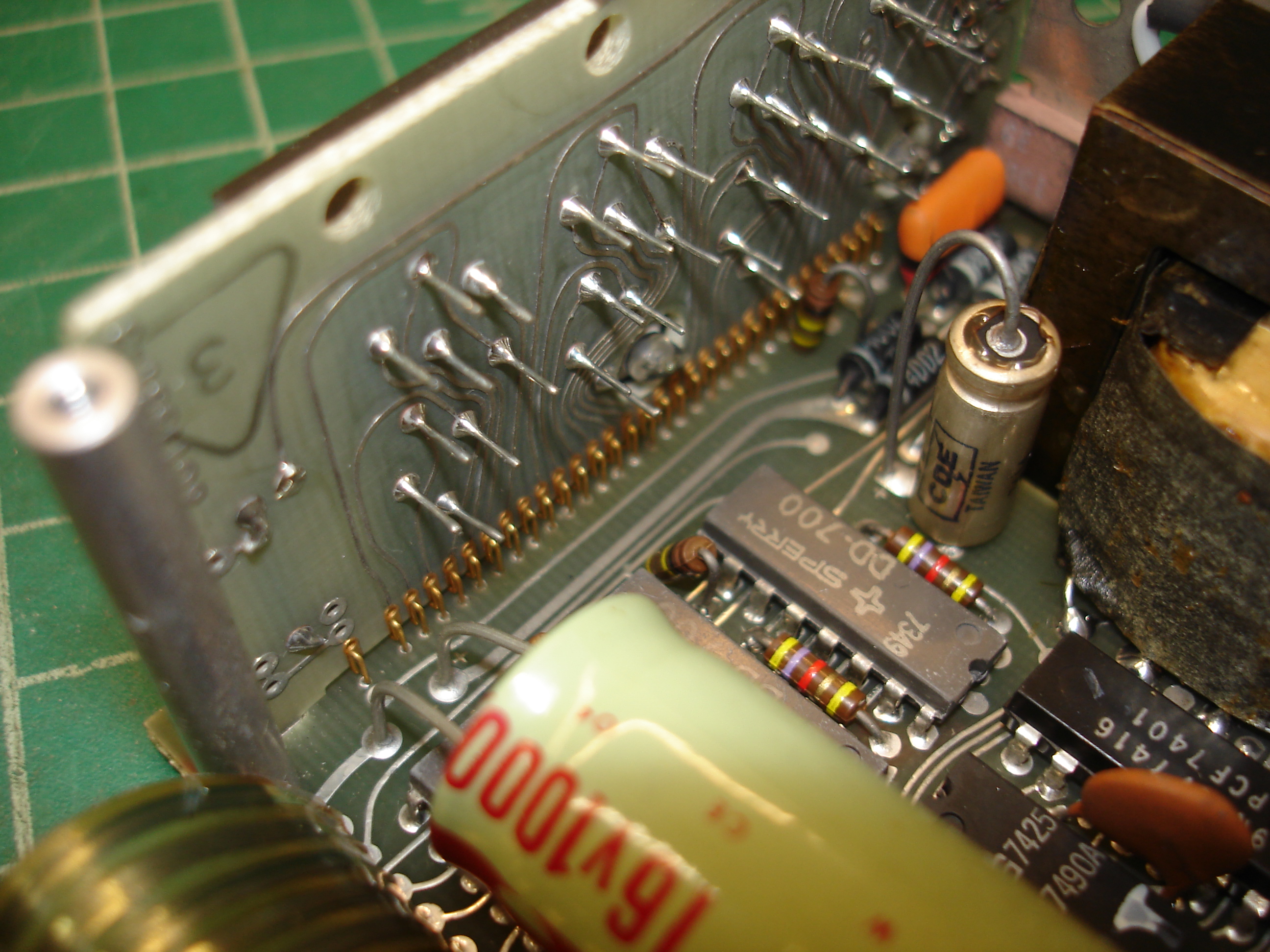
The Panaplex displays are driven by Sperry/Beckman DD-700 display drivers:
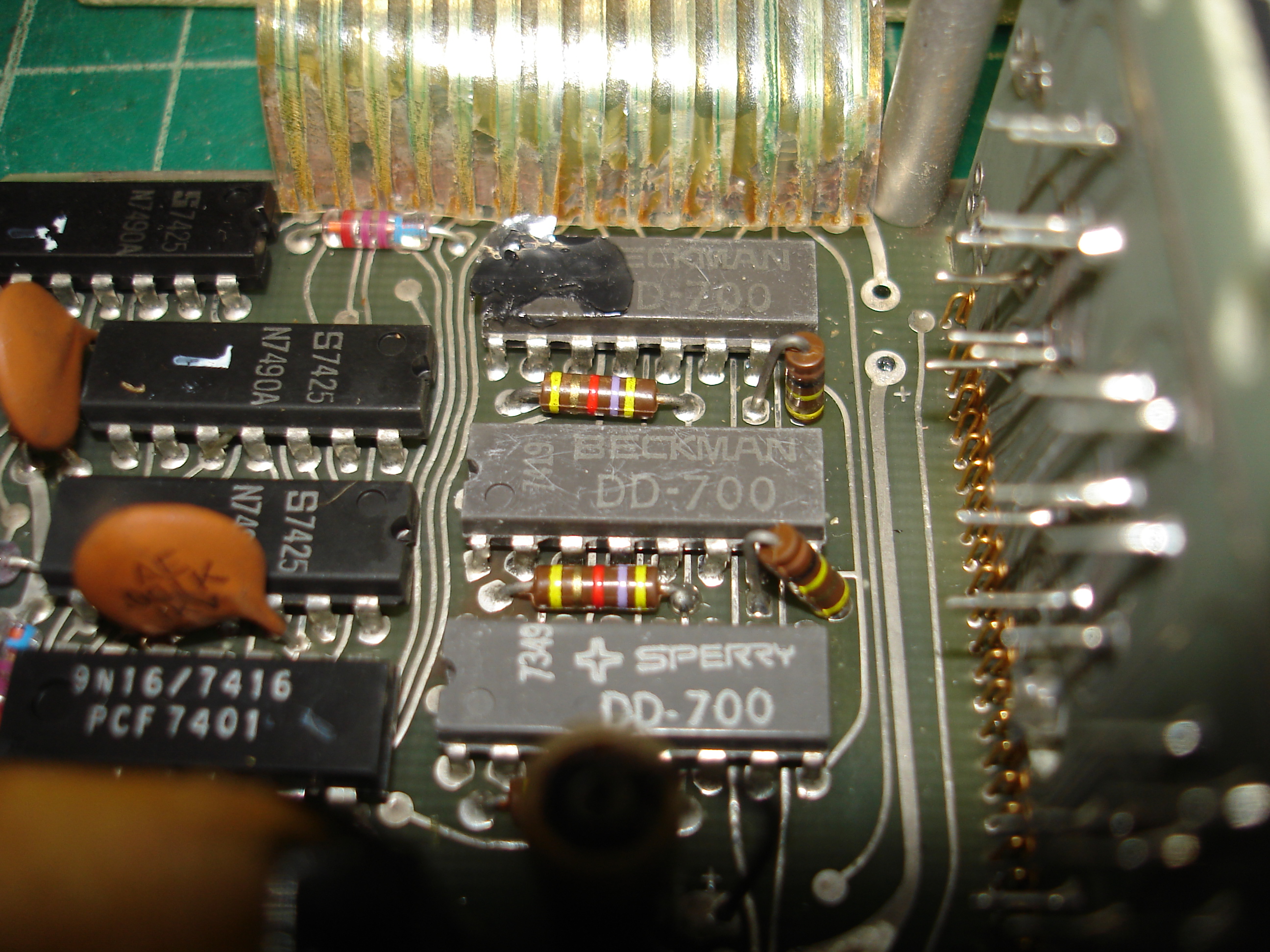
There’s a mix of Beckman and Sperry branding in this unit. These are direct-drive parts, they drive the cathodes of the Panaplex displays without intermediate transistors. DD-700s will also drive hexadecimal data, in addition to numbers 0 - 9!
The main reason for opening the meter was to make sure nothing was blown up before applying power, and to replace electrolytic capacitors. In my opinion, it’s not worth potentially blowing up rectifiers and/or the transformer for a shorted cap, or having something else damaged due to excessive ripple. The top board required a little consideration for its cap, since it is radial, but mounts horizontally:
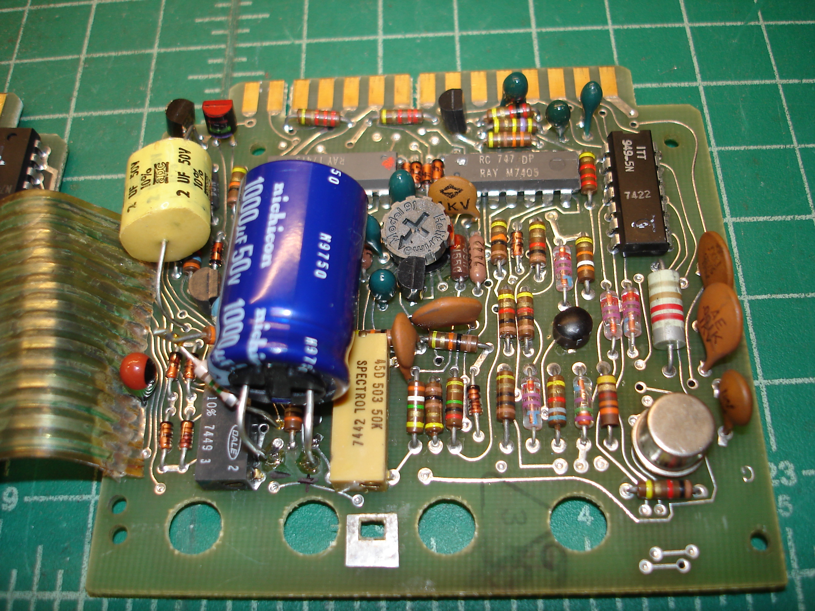
The calibration trimmers are also visible above. The yellow and black multi-turn pots control zero and proportional voltage accuracy. They are accessible through holes in the display circuit board, when the meter is assembled. I believe the small trimpot in the middle controls the integration time.
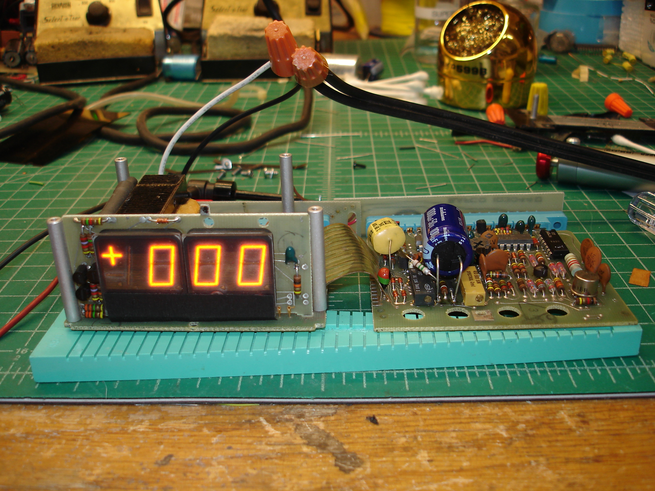
With all electrolytic capacitors replaced, the meter was brought up on a variac and checked for excessive current draw. After a warmup period, it could then be calibrated. I don’t have a manual for this panel meter, but typically the meter is warmed up, the inputs shorted, and zero point set, so we’ll do that first:
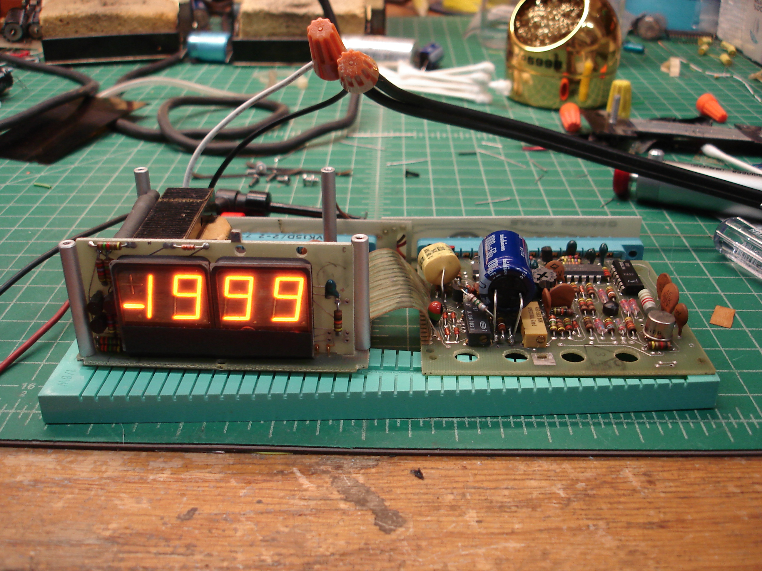
With zero set and stable, proportional voltage accuracy can be set. This is usually done at the positive top end of the range. These are 1500 mV meters, but most meters like this support overrange to 1.999 V. The meter was plugged into a stable DC power supply, with a calibrated Fluke 8842A in parallel. The DC power supply was adjusted for a reading of 1999 on the panel meter, and checked against the 8842A:

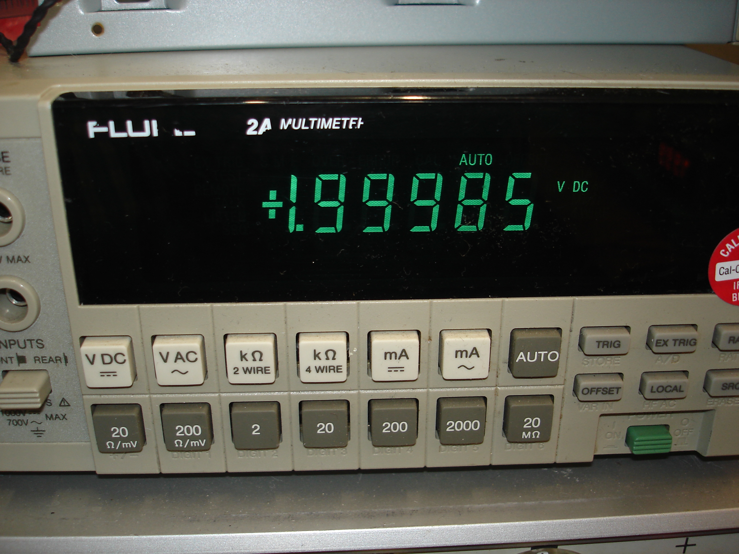
The panel meter was trimmed up for the positive reading. Next step is usually to flip the polarity and make sure the zero point is still stable at max negative reading. This checks for symmetry around the zero point:
Success! The panel meter could now be closed up and returned to its housing. Don’t forget to resolder the top tab on the display circuit board! The new capacitors were checked for clearance ahead of time, and fit nicely between the stacked boards:
Once reassembled, the panel meter’s calibration was checked with a known voltage:
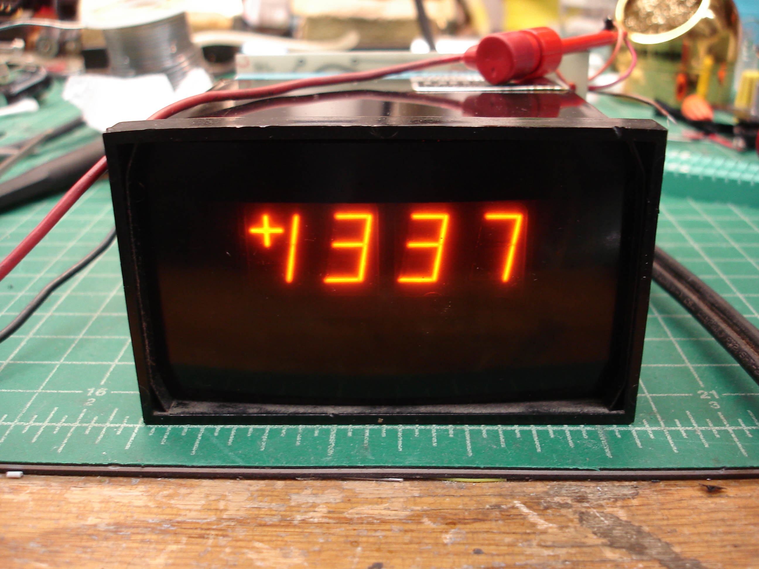
I believe the particular unit pictured in this writeup ended up with Connor Krukosky, as he needed a panel meter for some project and didn’t have any Panaplex gear.
volts