Topic: Hand Built Z80 Computer Cleanup and Run
Date: 2022 SEP 01
I purchased this interesting-looking machine from a friend at VCF East 2018. He’d picked it up at an estate sale in Albany, NY. Here’s the machine, basically as received:
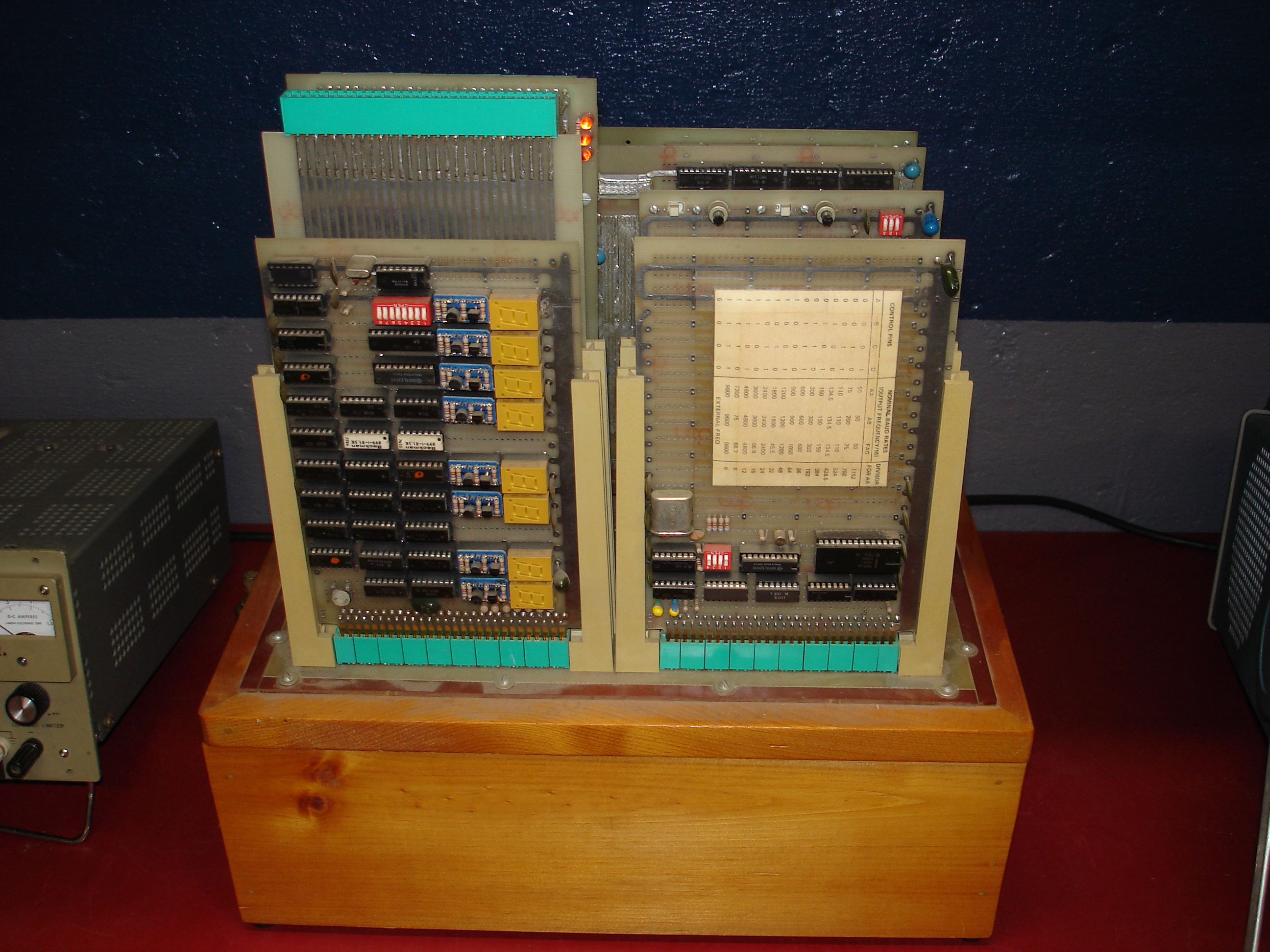
The system is constructed with a backplane mounted atop a wood box, which serves as the mounting base. It’s entirely wire-wrapped, with some etched power distribution. The overall construction quality is very high: it’s not completely clear if this is a homebrew, or someone’s take-home from a professional day job project.
The top of the box is hinged, and will lock in the open position at a right angle to the surface on which it sits:
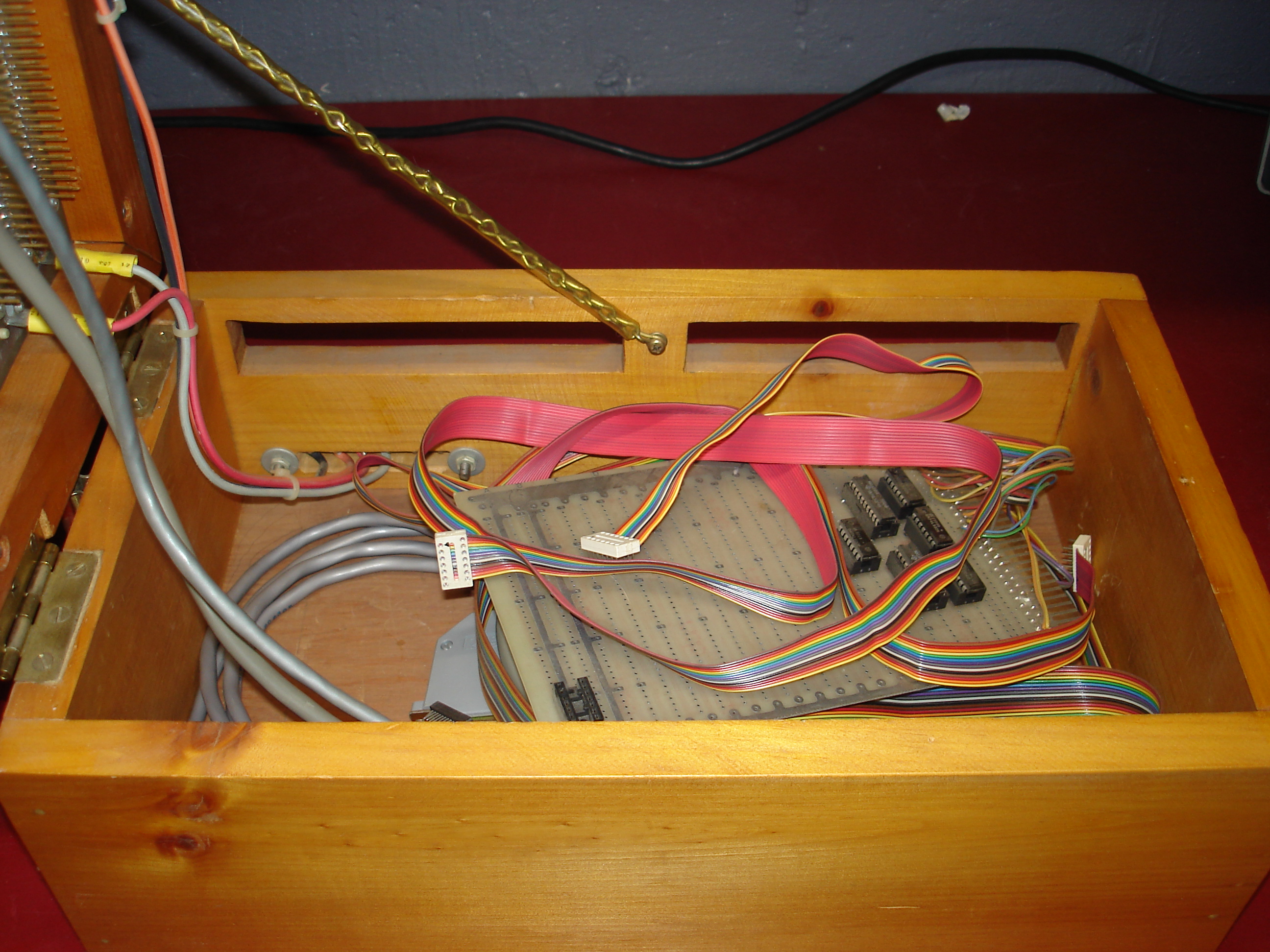
With the top opened and secured, the front panel board and USART bitrate legend are correctly oriented for easy reading. The bottom of the box offers storage for some of the system cabling, as well as extra boards, etc. The power input wiring is sufficiently recessed as to not pose a shorting hazard. With the top open, the backplane wiring is also easily probed:
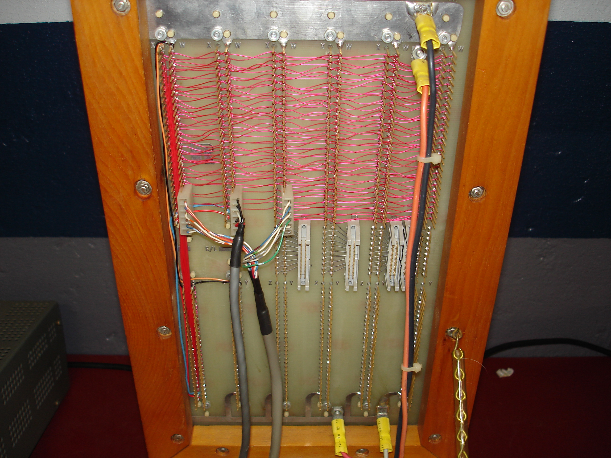
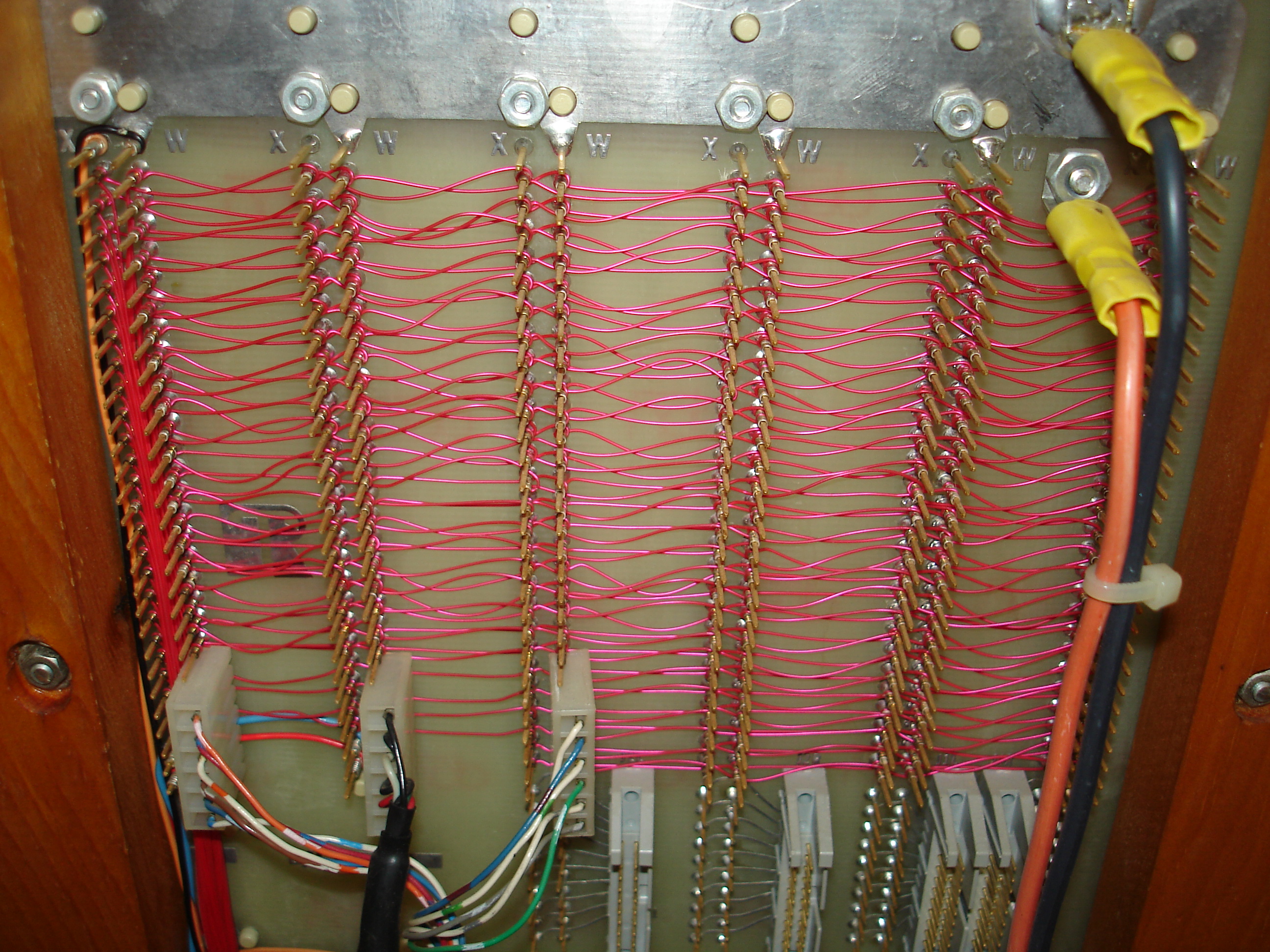
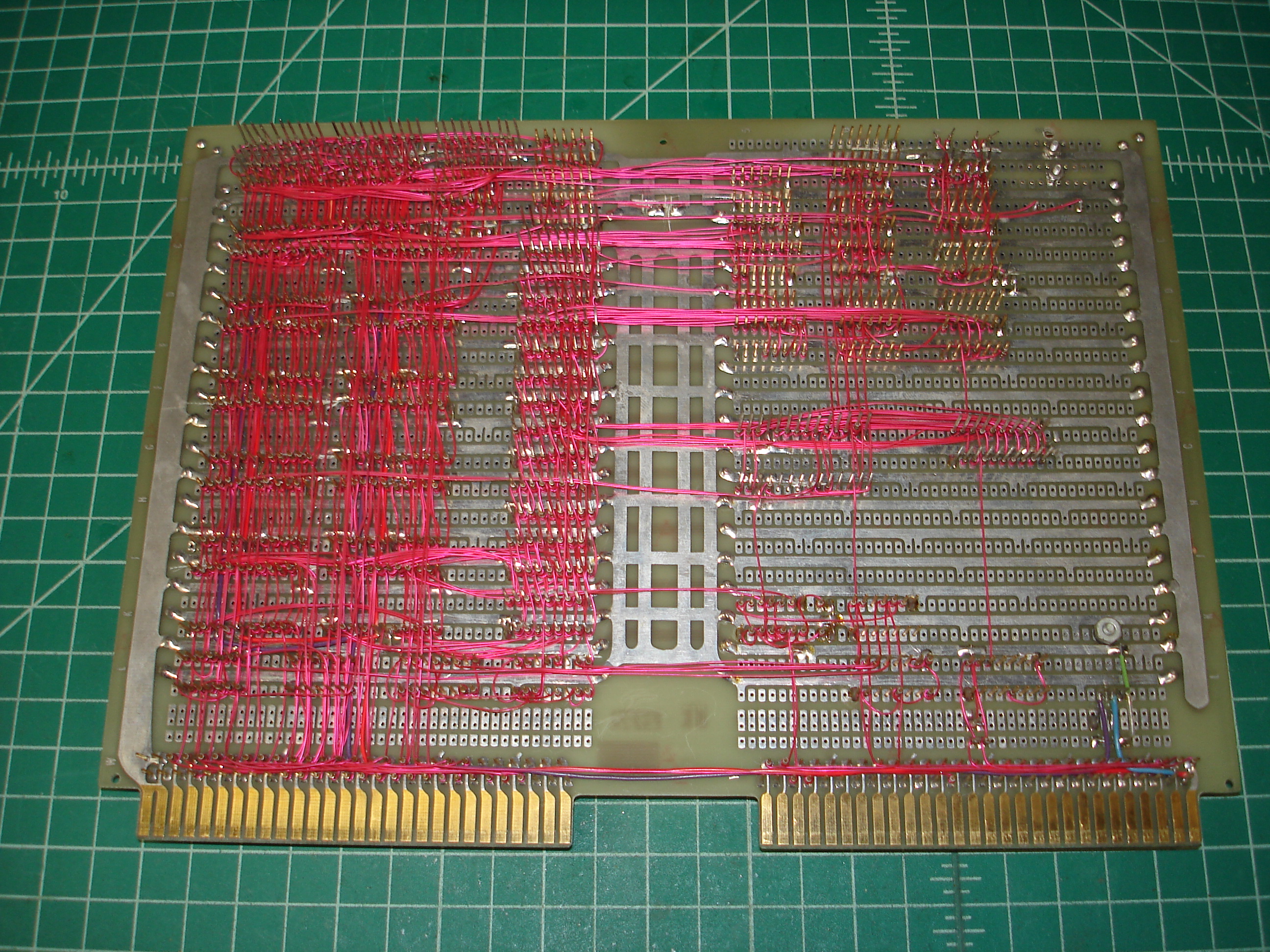
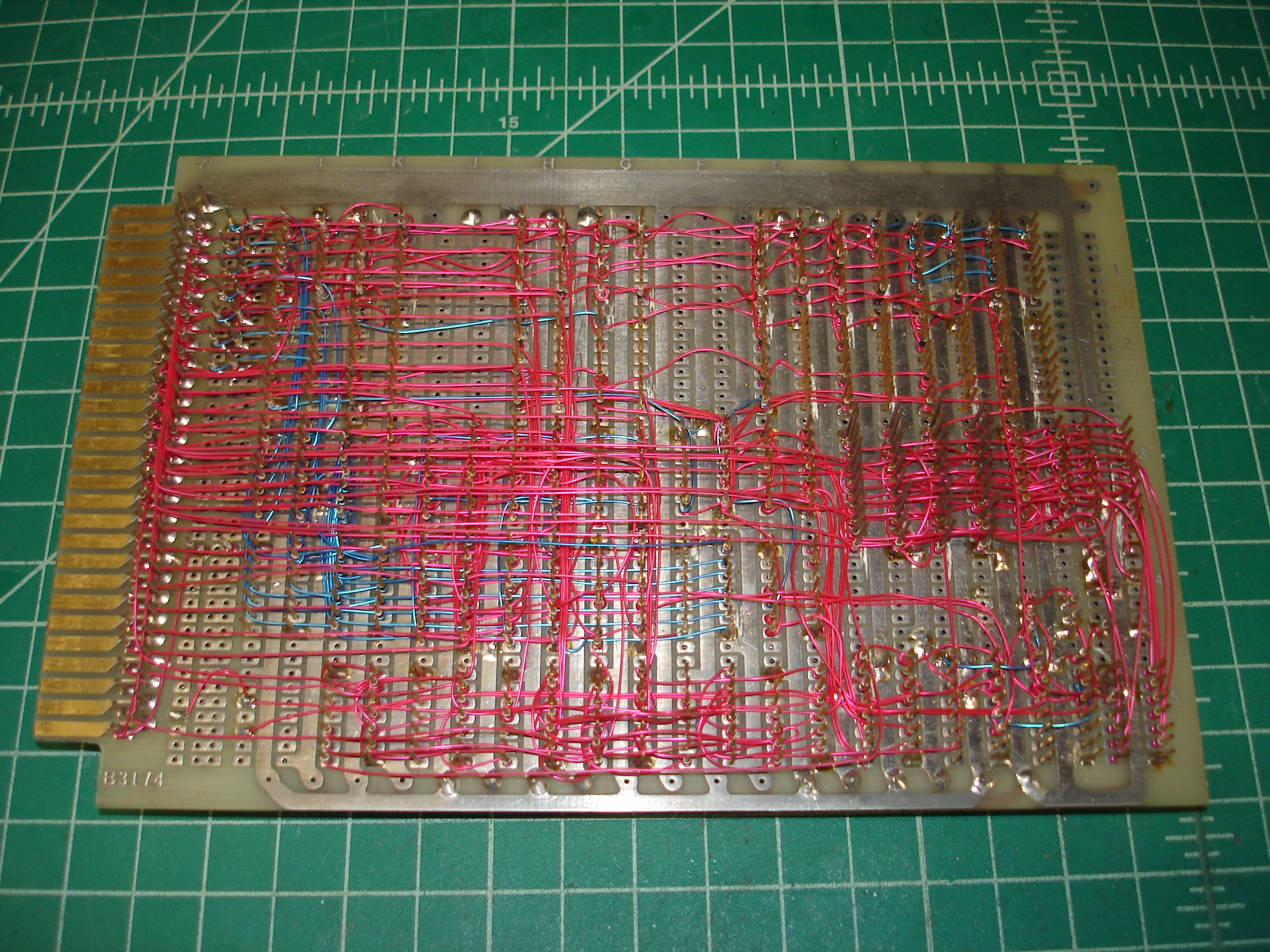
The entire system is wire-wrapped, with some of the power distribution running on etched traces. The wire wrapping is very neat, clearly done by someone who had done a lot of wire wrap construction. To me, it does not look like automatic/semi-automatic wrap, though it does mimic the layered structure often seen on boards that have been machine wrapped.
Since the system was in completely unknown operating condition, the first thing to do was remove all boards, clean them all, dump the EPROMs, and bring up a minimal configuration. We’ll go through each part of the system below.
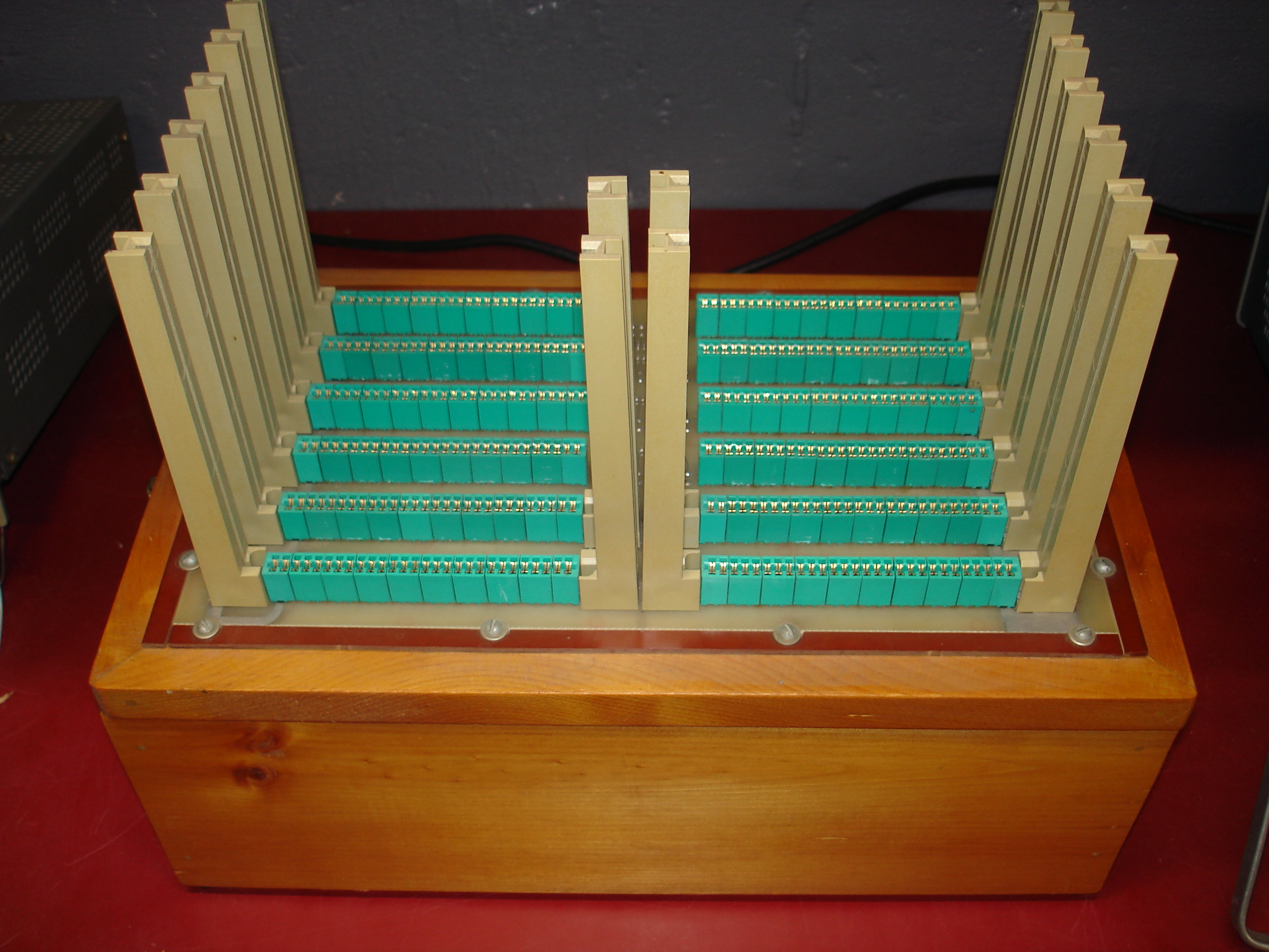
Card Cage and Base System
With all cards removed, the card cage was cleaned up, and new power wiring was added:
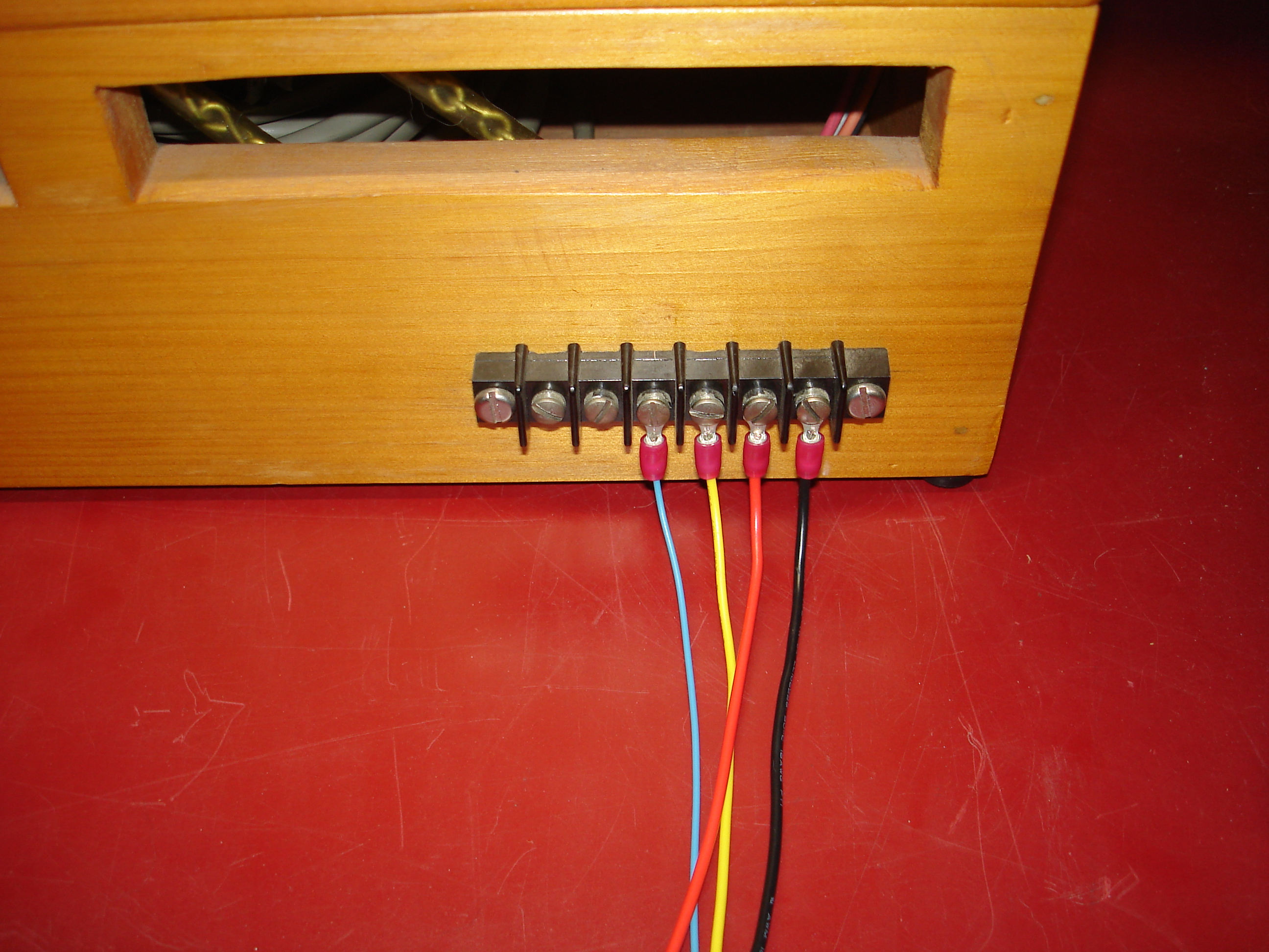
Power wiring was traced out from the CPU board using the Simpson 260 meter. The following colors are used:
- Black for ground
- Red for +5V
- Yellow for +12V
- Blue for negative supply
The negative supply only runs to RS-232 transceivers and a a -5V regulator on the CPU board, which provides -5V to the 2708 type EPROMs. During testing, -9V was used for the negative supply, which seemed to be fine.
Processor Board
This is the Z80 processor board:
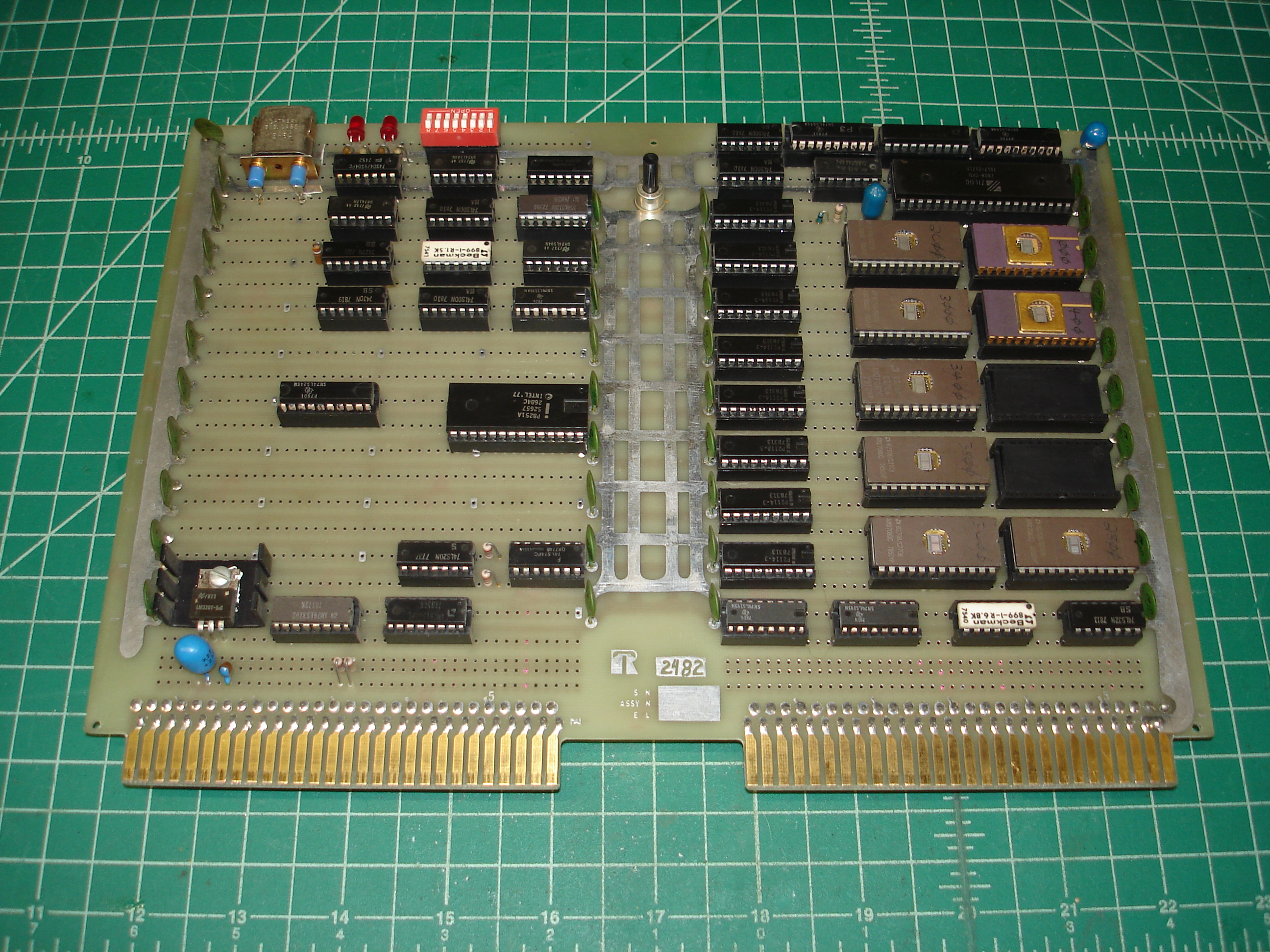
In addition to the Z80 CPU, this board contains 8K of populated EPROM (and two empty sockets), 4K of static RAM composed of 2114 SRAMs, an 8251A USART, and control/interface circuitry. The button in the top-middle of the board is the reset switch.
There’s a local -5V regulator in the bottom-left corner which provides -5V to the 2708 EPROMs. These are old triple-voltage parts, meaning that all three rails are definitely required for operation.
There are no RS-232 level shifters for the USART on the CPU board; presumably, it talked to the outside world at TTL levels.
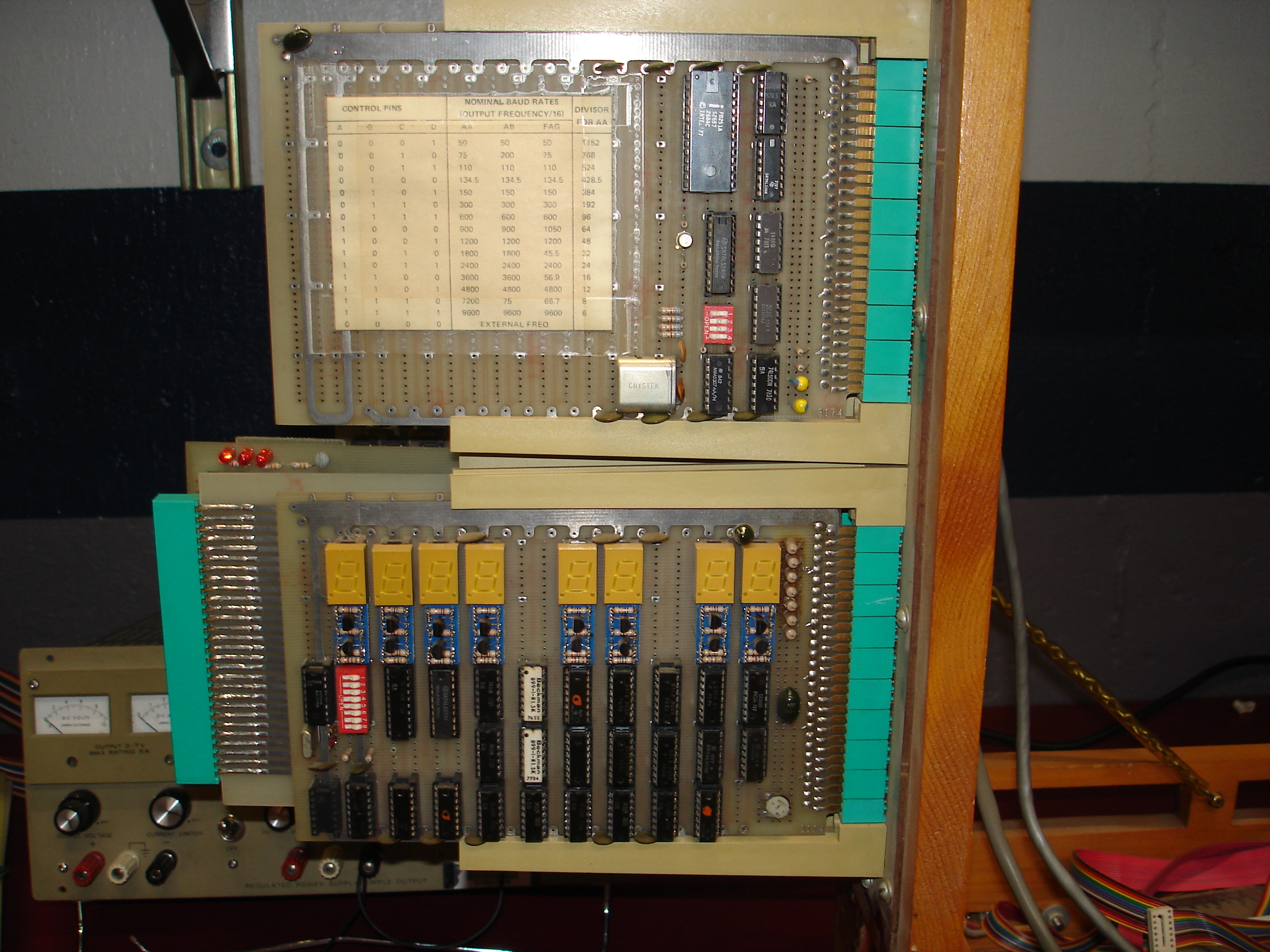
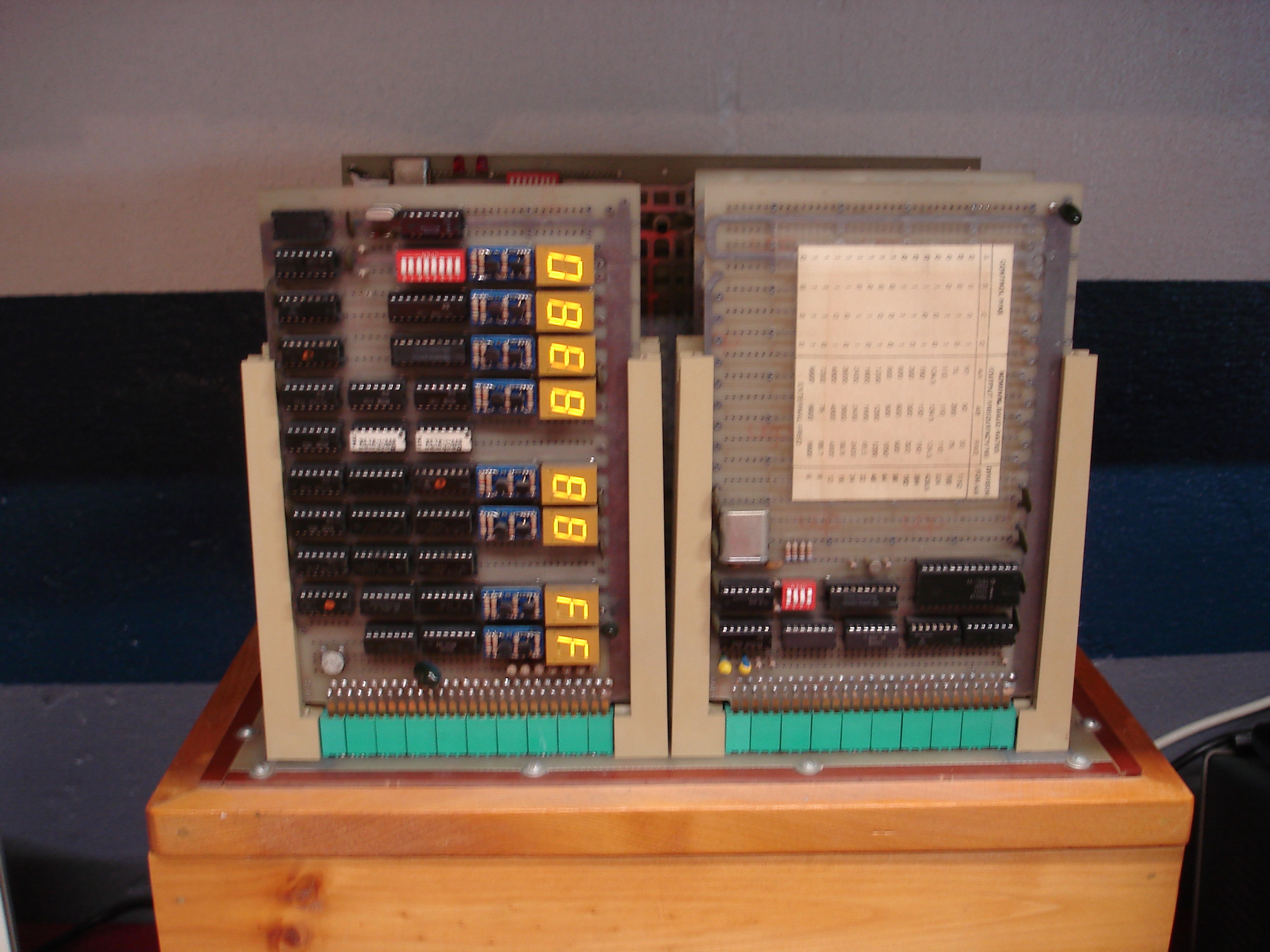
Front Panel Display
A small front panel display board is installed in the first slot:
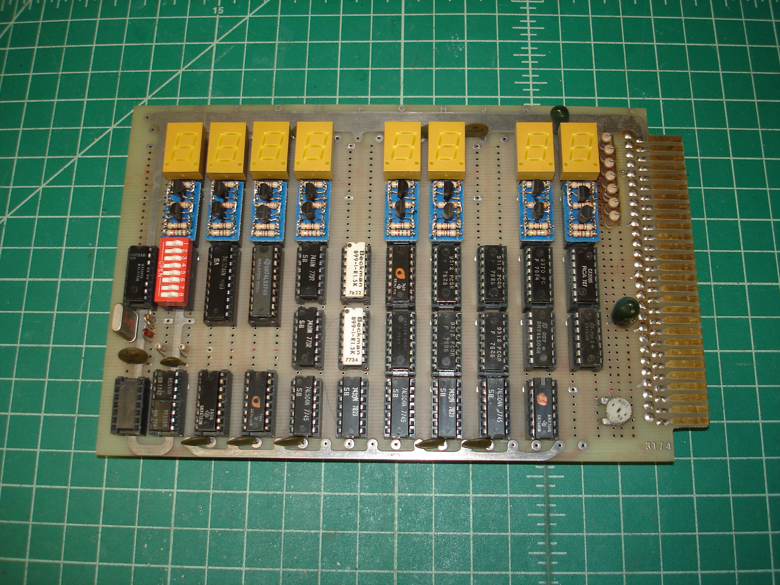
The front panel is meant to be viewed with the top of the system open, presumably to allow simultaneous reading/operating of the front panel and backplane probing. The seven-segment displays are driven as hex displays. The resistors near the card edge show signs of overheating.
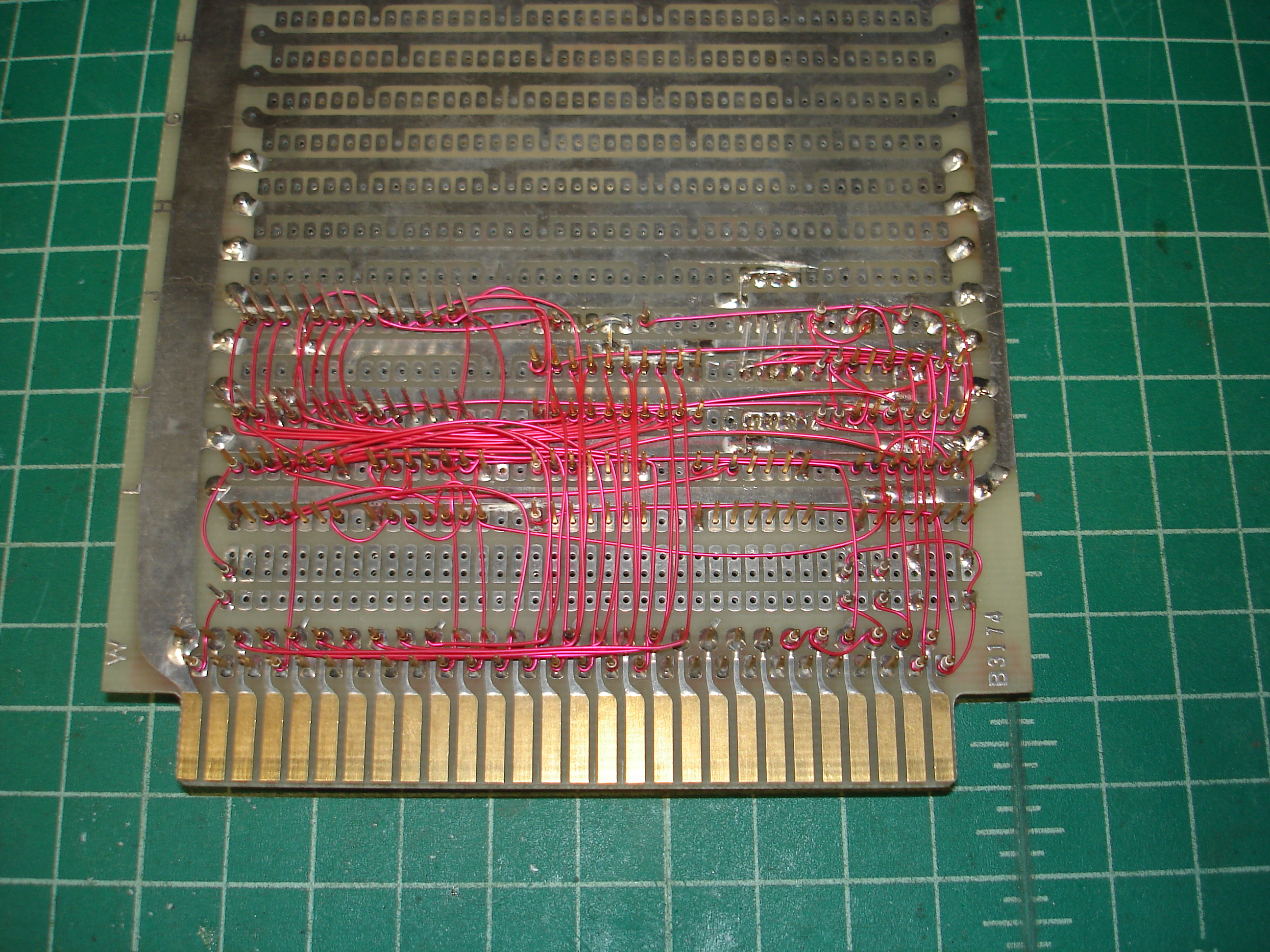
Single-Step Board
The function of this board was initially unknown, but it was later determined to be run/halt and single-step control:
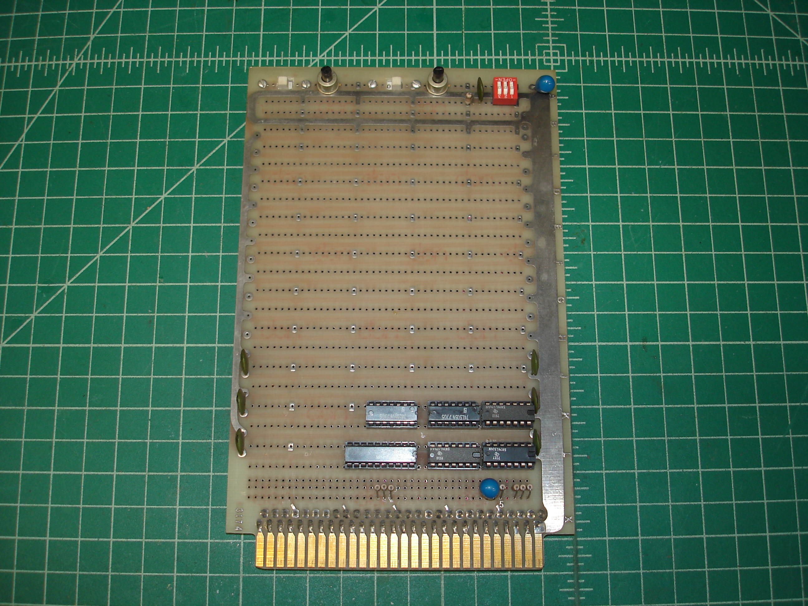
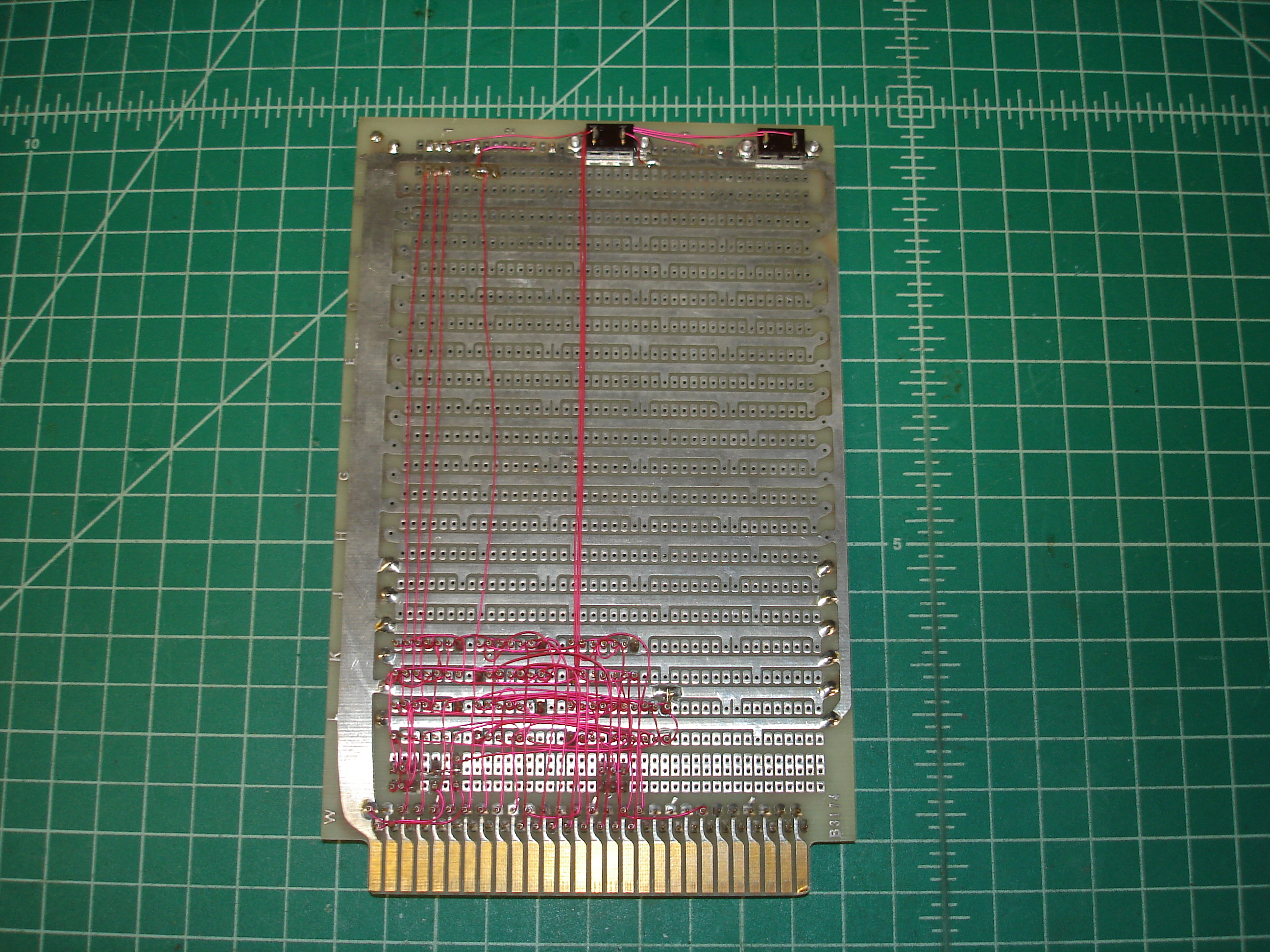
The run/halt and single-step both work. When used with the front panel display, this allows tracing and debugging programs running on the Z80.
RAM Board
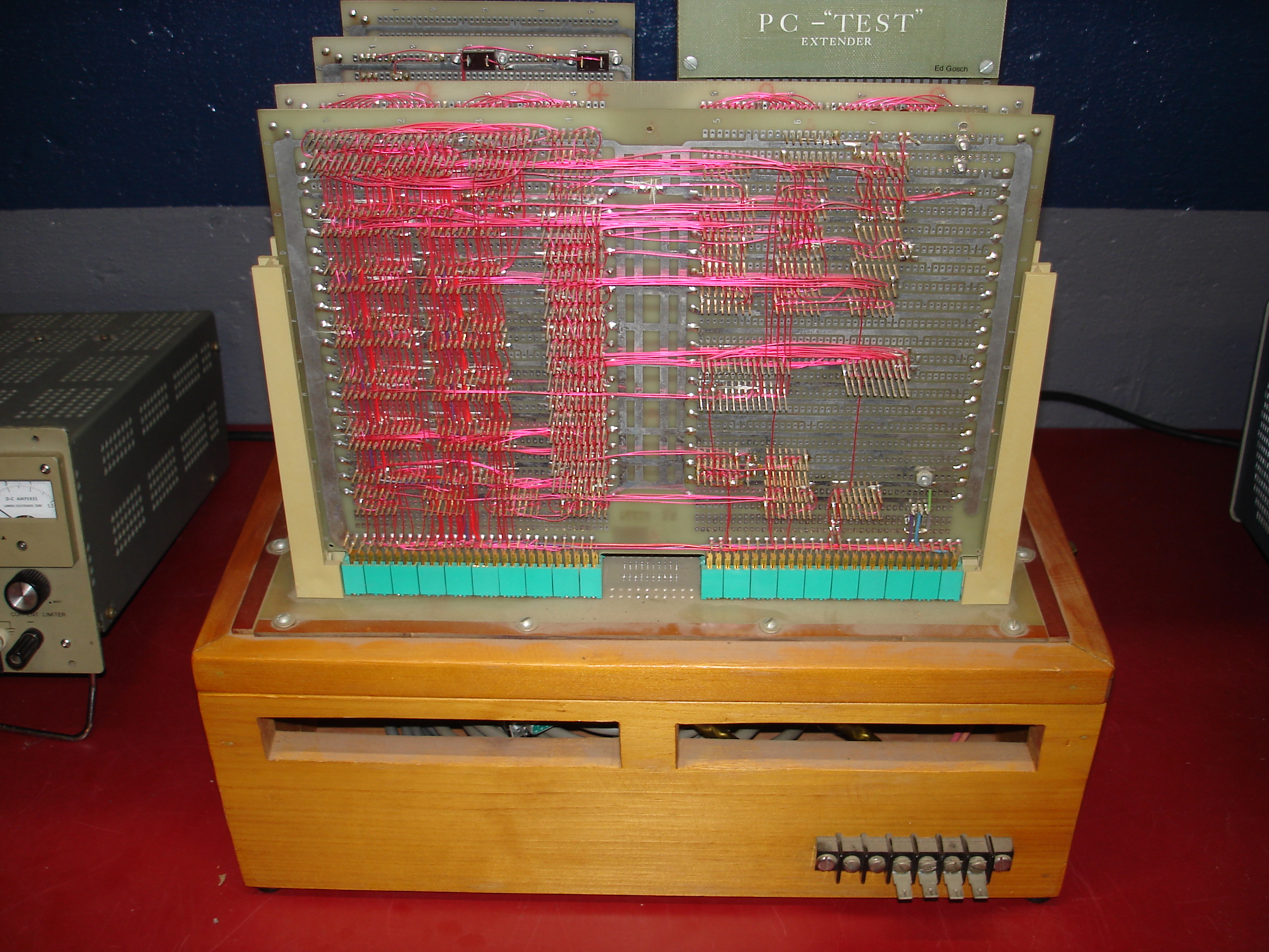
In addition to the 4K of RAM included on the processor board, the system includes an expansion RAM board:
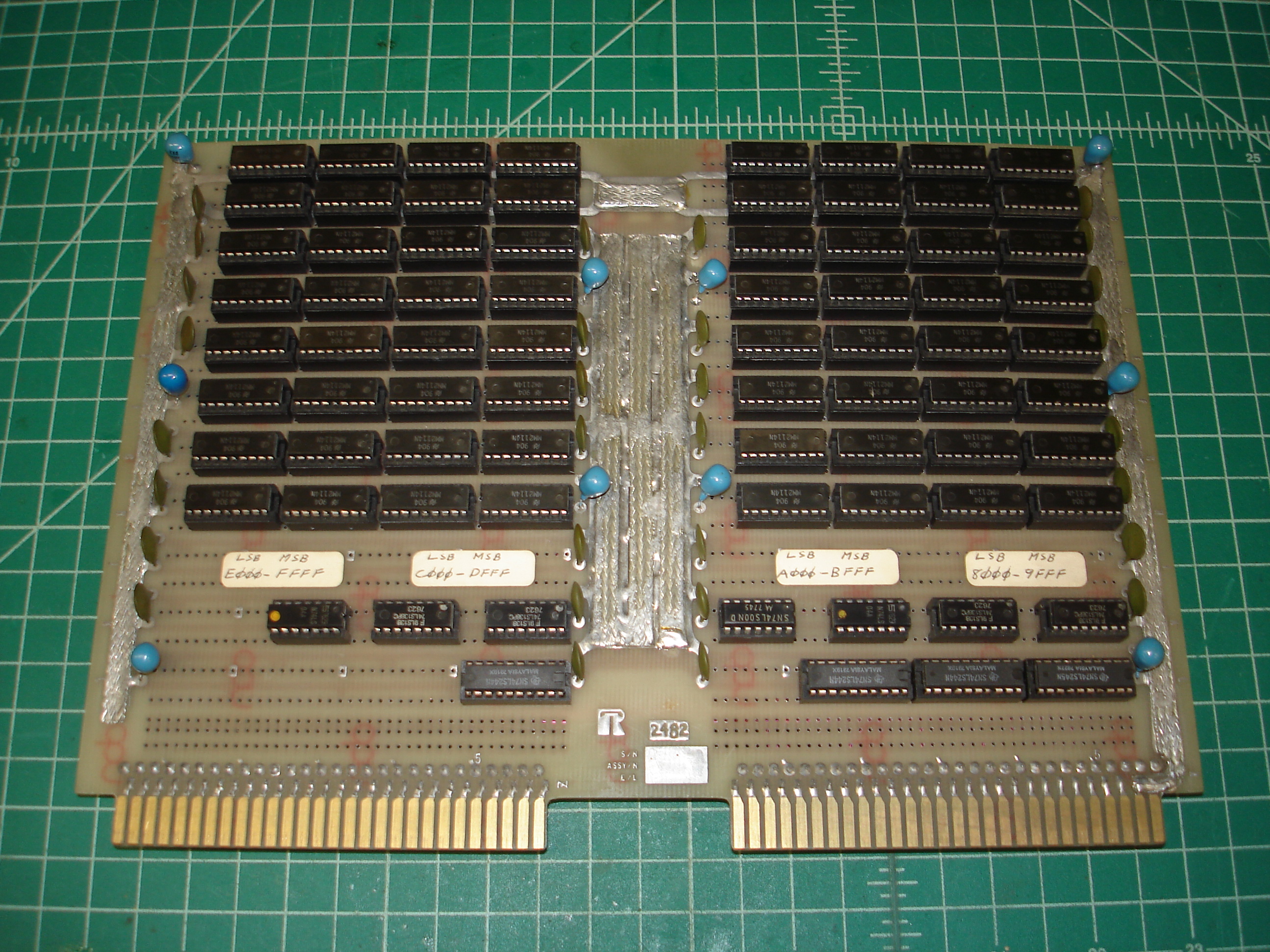

What a board! The power and ground planes have been reinforced with copper braid. The board contains an entire 32K of 2114 type static RAM! It probably draws two to three amps all by itself.
The RAM board also includes a possible hint at the origin and creation time of this system:
I haven’t found any information regarding this logo, and would appreciate anything at all about it! There appears to be a datecode next to it, suggesting the base board was at least fabricated in mid-1982. Who knows if that’s when it was wrapped.
USART Board
This board contains an Intel 8251A USART and associated circuitry, including RS-232 level shifting. It turns out to be the system console board, and the RS-232 signals exit the chassis through the backplane and a DB-25 connector:
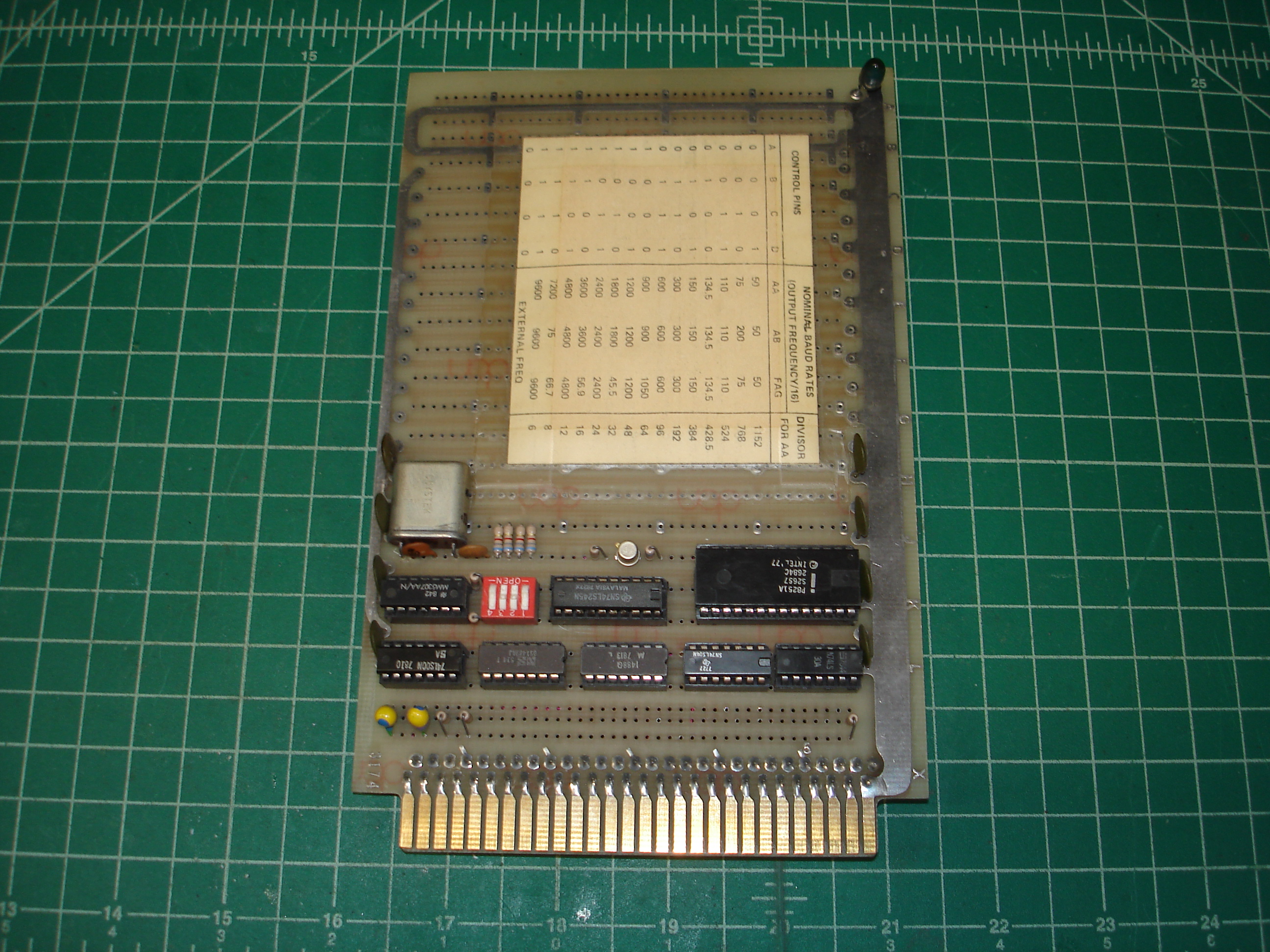
The USART board has a bitrate table glued to it:
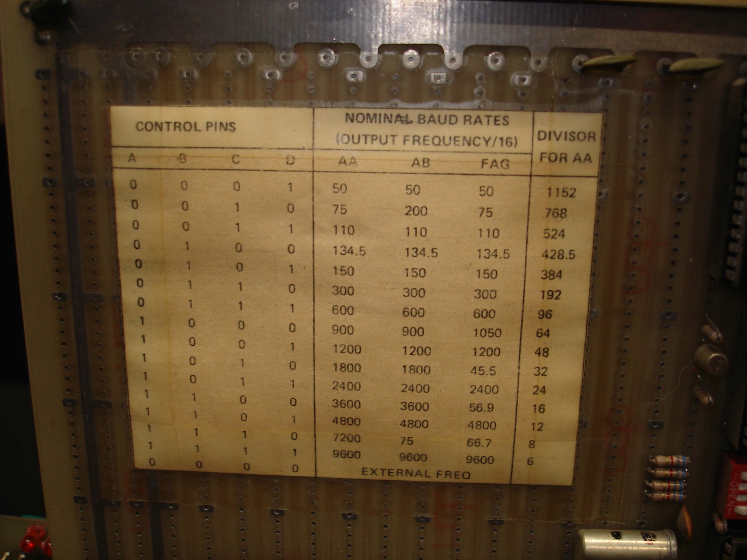
Like the front panel display, the bitrate table is oriented to be readable when the top of the system mounting box is open.
Extender Boards
Two extender boards were included with the system: a straight-through extender, and one with DIP switches to allow isolation of signal lines:

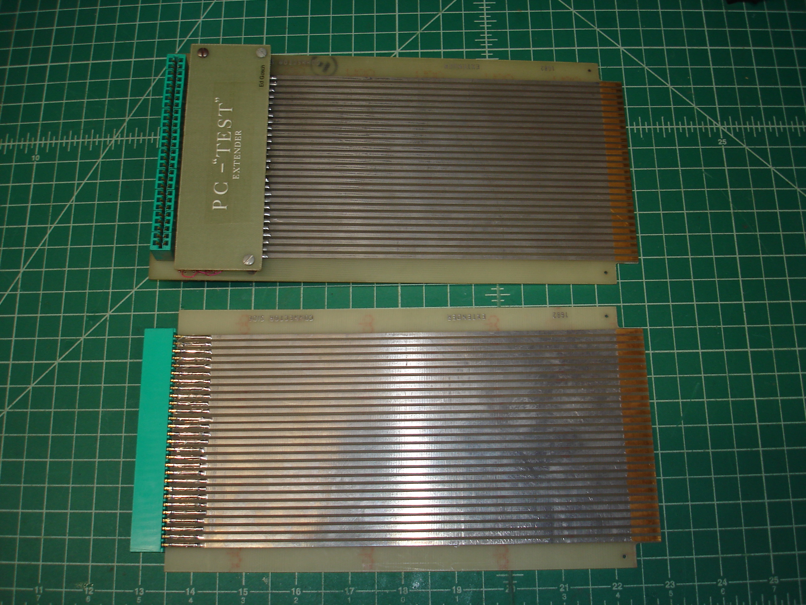
One of the extenders includes a label on the protective shield on the back side:

The meaning of PC-"TEST" is unclear. The name in the corner, Ed Gosch, matches with a silent key amateur radio operator, W2UV, who lived in the Albany area. Perhaps Mr. Gosch was the creator of this well-built system?
Reassembly and Testing
With all of the boards cleaned, a minimal system was configured with the CPU board, USART board, and front panel board. The new power wiring was connected to my Lambda triple-voltage adjustable power supply, and each rail was brought up with current limiting, in an effort to catch any shorts. No shorts were found, and the system came up:
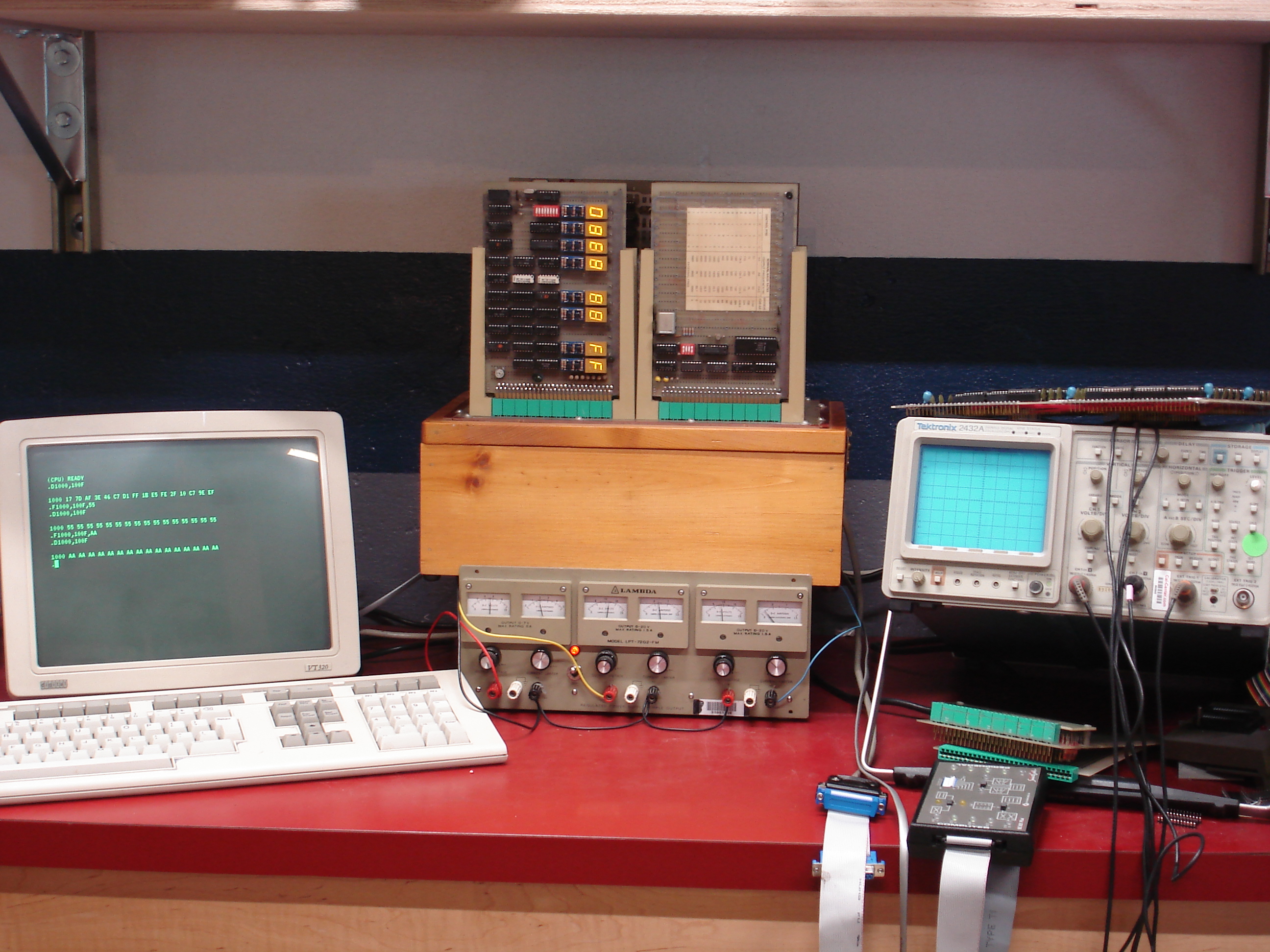
A DEC VT320 was used for the system console. After pressing RESET, a ROM monitor came up on the console serial connection:
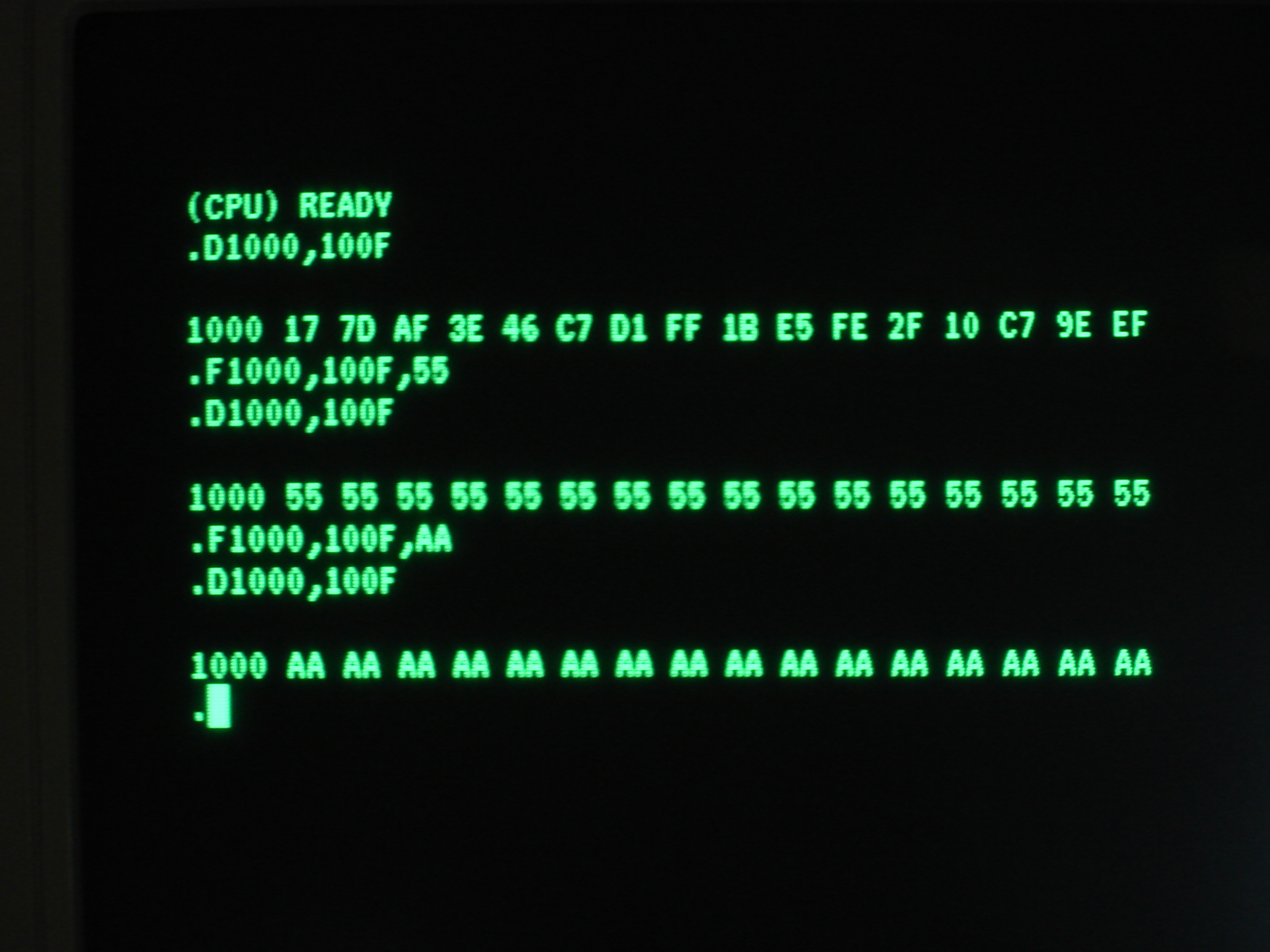
The monitor signs on with (CPU) READY. It responds to commands with syntax very similar to that used in TDL’s Apple and Zapple monitors. I suspect the monitor is either heavily influenced by one of TDL’s, or is in fact a customized version. I have not yet disassembled the contents of the EPROMs.
The front panel and run/halt/single-step functionality also works:
The resistors on the front panel do indeed get quite hot!
Conclusion
I expected more of a challenge in getting this hand-built Z80 system running, but nothing more than cleaning was required. This is probably a testament to the quality of its initial construction, more than anything. The 32K RAM board has not yet been tested, but chances are good that there are some bad SRAMs in there, given the quantity present.
The system does have free slots in the backplane, which could be used to add peripheral hardware, such as mass storage, parallel I/O, etc. There are a few other cards with minimal circuitry on them which also need to be explored.
wire wrapped computers fixed