Topic: Repairing and Interfacing a Fairchild F8 Kit
Date: 2018 JUL 01
Quick Links
- Vintage Computer Forums thread from 2011
- Fairchild F8 Kit information on BitSavers
- Veras Systems F8 Kit Manual on archive.org (this is identical to the Fairchild F8 Kit)
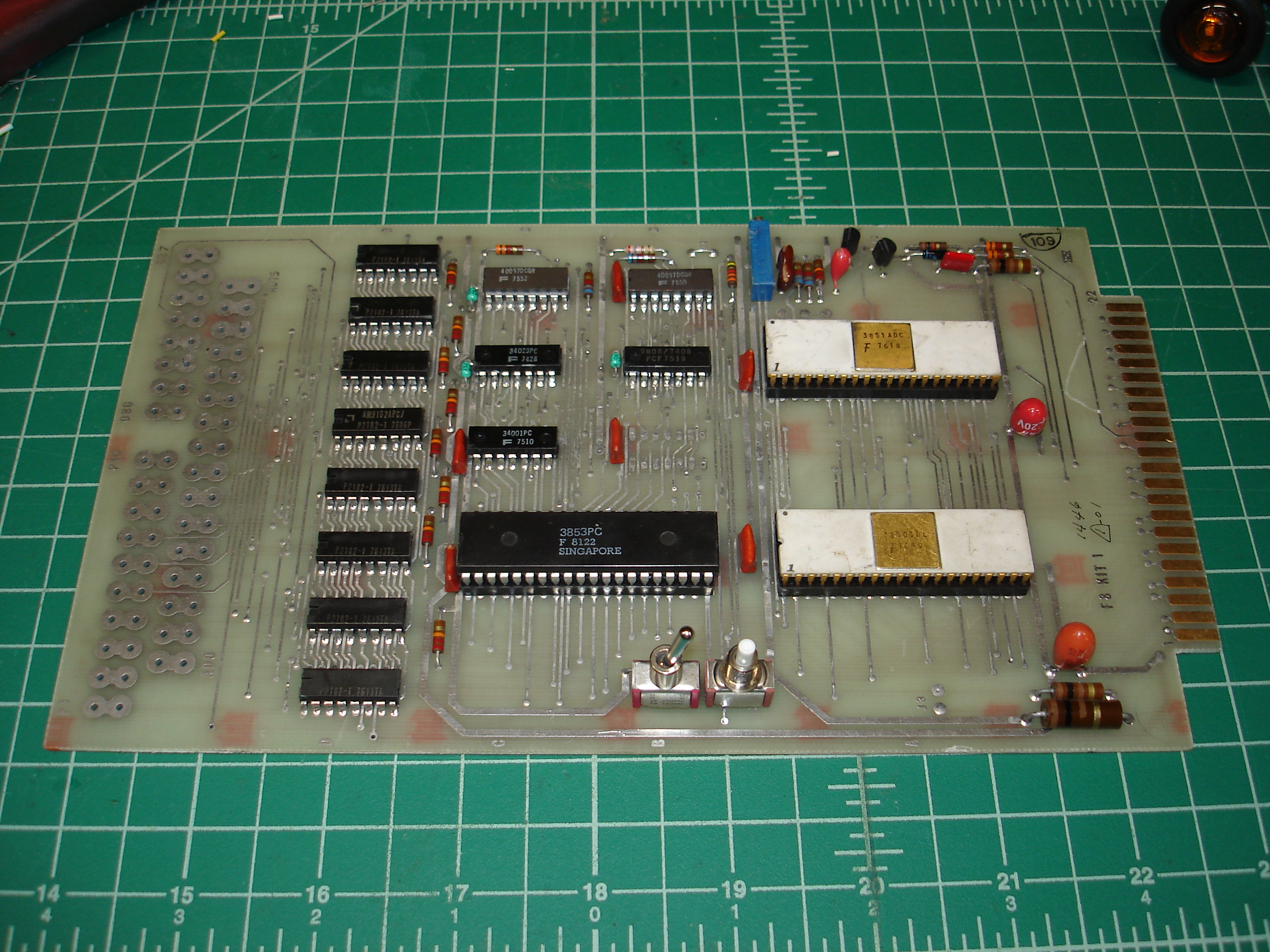
I acquired my Fairchild F8 Kit in a large lot of industrial scrap. It was in poor shape, having been thrown in with scrap, and two of the 40-pin ICs had been scavenged, likely prior to it being thrown in the scrap heap. The reset and toggle switches were both busted off, as were a few capacitors and resistors. Fortunately, the mask-programmed 3851A PSU (Program Storage Unit) IC was still in the board, so I decided to try and revive it.
I replaced a number of decoupling capacitors, a resistor, the two broken switches, and found replacements for the missing 3850 CPU and 3853 SRAM interface. I happened to have a white ceramic 3850 CPU salvaged from a piece of broken avionics gear. The 3853 SRAM was sourced from one of my usual IC suppliers. I was able to find the assembly manual on archive.org – it states that it is for the Veras Systems F8 Kit, but apparently this kit is identical to the Fairchild F8 Kit. The schematic can be found on BitSavers.
I wired up a Vector R644 22/44 pin edge connector: this is a standard 0.156” spacing edge connector, as found on many systems from the 70s and 80s. The F8 Kit requires +5V for logic, and +12V for its current loop interface. I’d initially attempted to wire the current loop interface into the 20 mA current loop port on my VT220 terminal, but was having no luck. Initially, I did not have the Veras Systems manual, and missed the part about connecting the current loop interface to the I/O pins used for bit-banged serial I/O. To use the onboard current loop interface, one must connect:
- Pin 10 to pin 14
- Pin 12 to pin 15
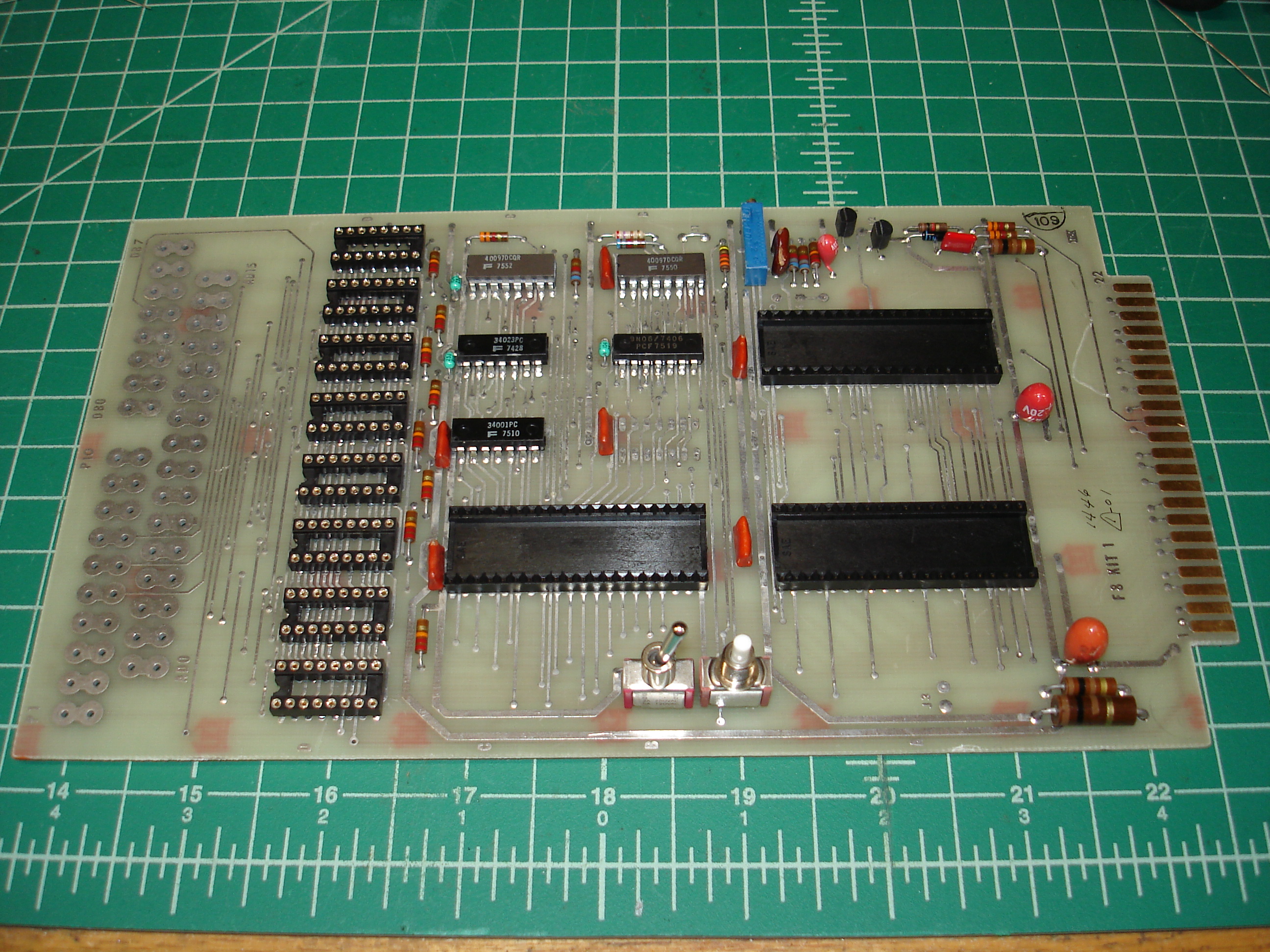
This still didn’t work for me, so I built a small MAX232 circuit on a bit of breadboard and connected it to the TTL level I/O pins used for serial I/O. Still no luck! I could tell the board was trying to bootstrap, as it arrived at the correct addresses, visible by probing the address lines on the end of the board opposite the 22/44 connector. No amount of twiddling of the system clock trimmer would produce the correct sign-on prompt, though it did produce output. I suspected bad RAM, so I desoldered all eight 2102 1K x 1 bit SRAMs and replaced them with sockets:
Even with a known-good set of 2102s borrowed from one of my other systems, I was getting the exact same symptions. I suspect this was due to the TTL serial data needing to be inverted on at least the transmit line; however, I never got to that point. I re-read the manual and discovered I’d misread the schematic: PRINTER OUT was supposed to be pin M on the 22/44 connector, but I’d misread it as 3! I reconnected the current loop interface to the VT220 and was greeted with an operational monitor:

Correct wiring to the VT220 current loop port is as follows:
- F8 Kit pin 1 to VT220 pin 5
- F8 Kit pin 2 to VT220 pin 3
- F8 Kit pin 13 to VT220 pin 2
- F8 Kit pin M to VT220 pin 7
Replacing the RAM did result in an interesting discovery, for anyone doing diagnostics on a F8 Kit in the future: no working RAM is required for the FAIR-BUG monitor to sign on and work properly, it appears to use the F8’s internal scratchpad registers exclusively for its operation. No need to chase bad RAM if FAIR-BUG doesn’t sign on, and the monitor itself can be used to isolate which RAM chip is bad, if there is in fact a RAM fault.
I ended up guessing the adjustment of the system clock oscillator: I twiddled the adjustment pot while watching the VT220 screen, and noted approximately where the FAIR-BUG question mark prompt started to be printed incorrectly. I picked a spot in the middle and left it there. I haven’t verified frequency of the main clock yet, but it seems to be happy with this choice. It’s possible to strap the system for console operation at 300 bps instead of 110 bps, apparently the system clock was close enough for this as it worked correctly at 300 bps with my VT220.
For now, the Fairchild F8 Kit gets used with my Lambda triple-voltage bench supply:
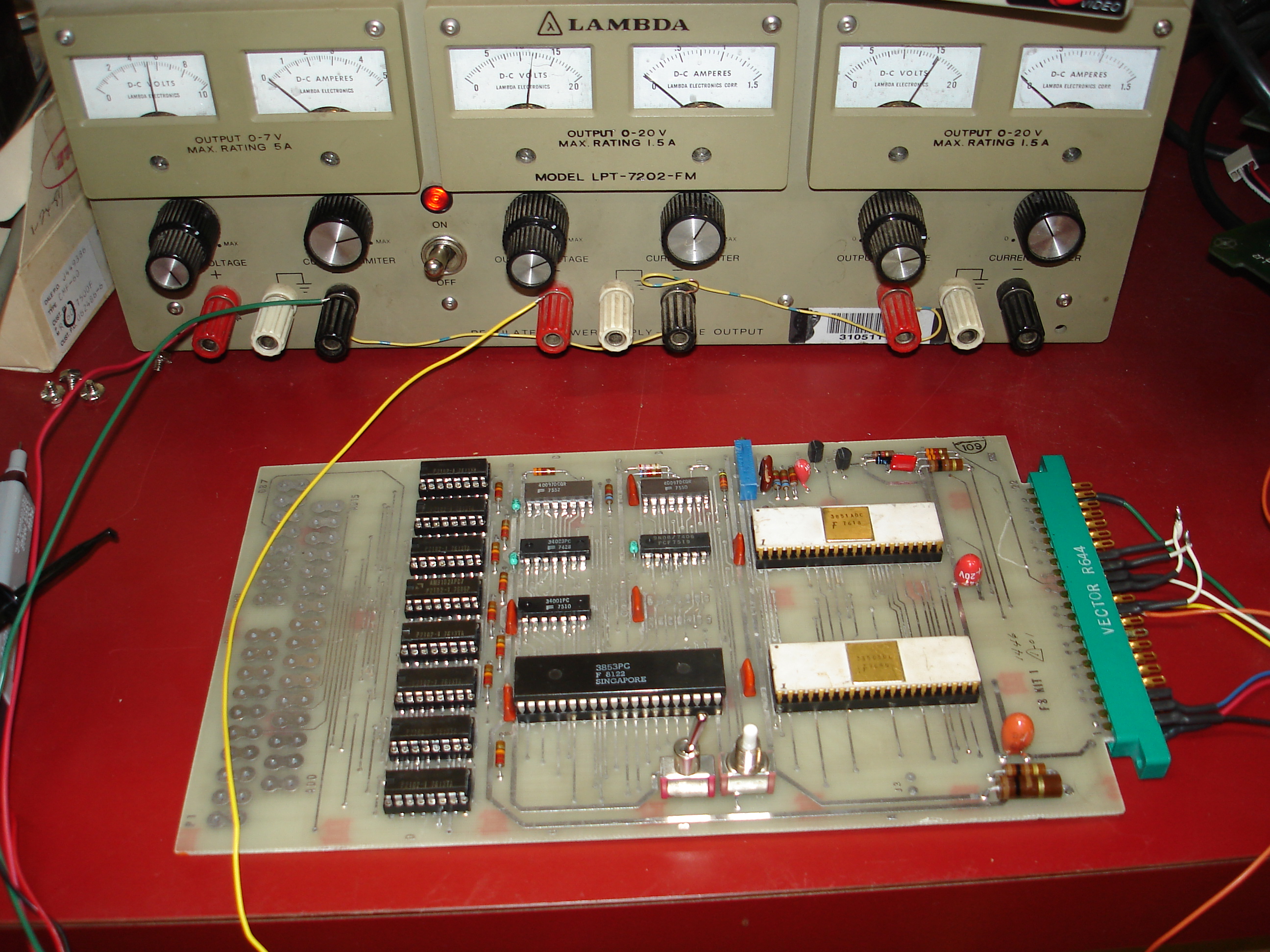
I will likely build it a more permanent home with its own self-contained power supply, but for now, it lives on the benchtop! I’d like to find a white ceramic 3853 SRAM interface to go with it, if anyone has one they’d like to part with, please contact us.
F8 kits restored