Topic: Building a replacement module for the DS1244 32K NVRAM/RTC
Date: 2018 MAR 17
Dallas (now Maxim Semiconductor) produced many NVRAMs and battery backed RTCs, and it seems I’m slowly having to replace each model in their entire lineup! While working on a DECbrouter 90T1, a piece of networking hardware from the 90’s, I encountered a DS1244, which is a 32K NVRAM with “Phantom RTC.” This device is still sold by Maxim, but is somewhat expensive, and will eventually also die, requiring replacement of the module. In the DECbrouter 90T1, the module is soldered, and there is no room for a socket. So, rather than rework a vintage board several times to replace an expensive legacy module, I designed a replacement.
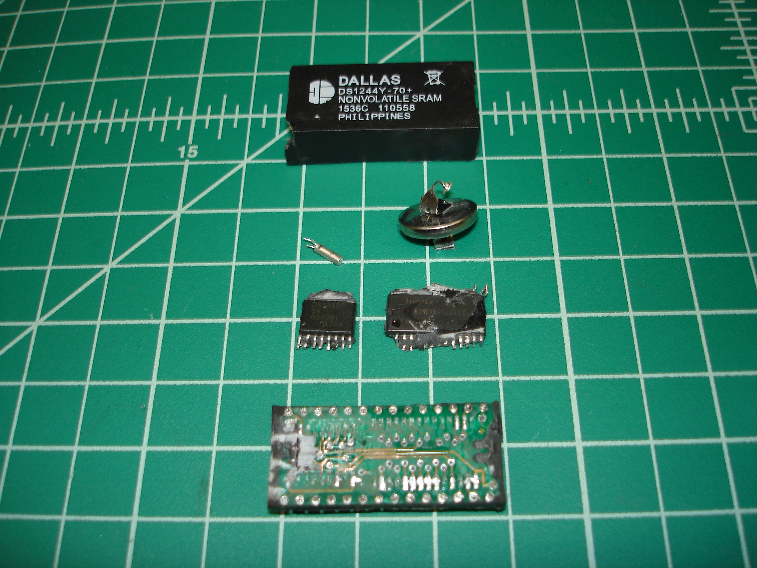
The first step in making a replacement was figuring out what was in the original. I ordered two DS1244Y modules from an IC reseller in China for destructive disassembly. As an aside, these were listed as new and came with a 2015 datecode, but the lithium cells inside were dead. Typical relabels! Good thing I planned on smashing them…
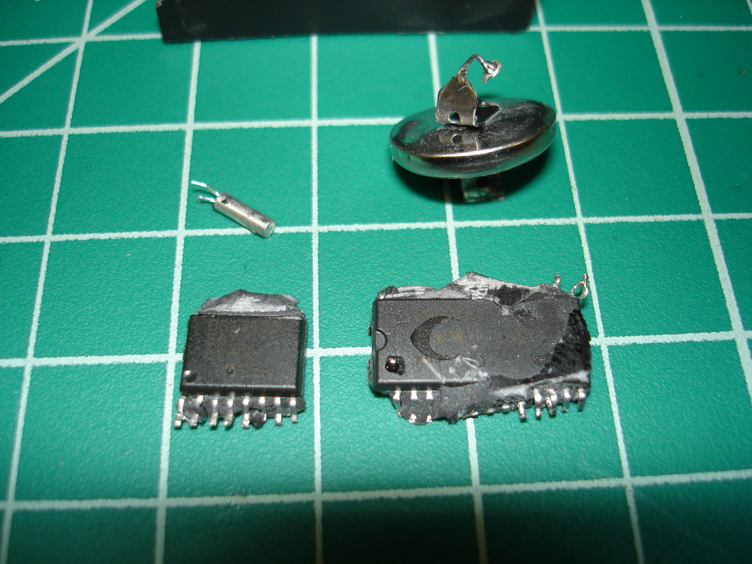
The DS1244Y was opened by removing the potting shell, then making cuts with a hack saw on all four sides, and wedging the encapsulation apart with a cold chisel and a small ball peen hammer. The module is just a 62256 JEDEC type SRAM with a controller, a 32.768 KHz crystal, and a lithium cell. The controller chip is of course the “secret sauce” in the module. It turns out that the controller is a Dallas/Maxim DS1315 Phantom Time Chip, which is still in production. It’s a fairly expensive IC, but cheaper than buying a new DS1244 module.
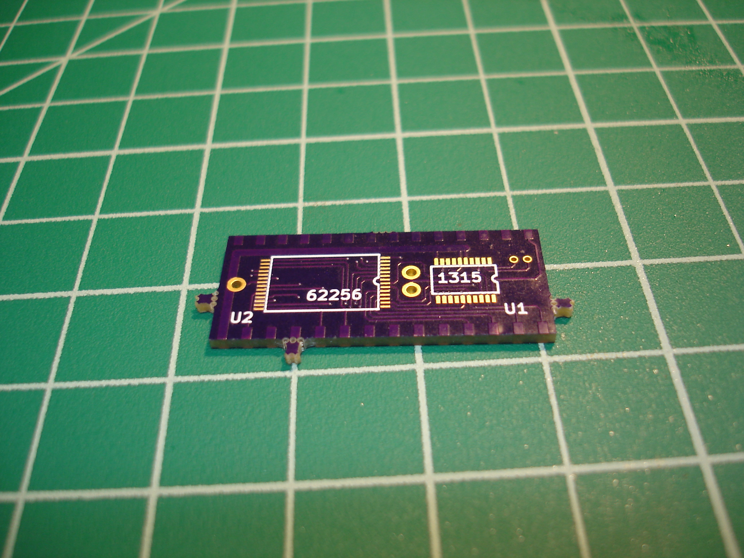
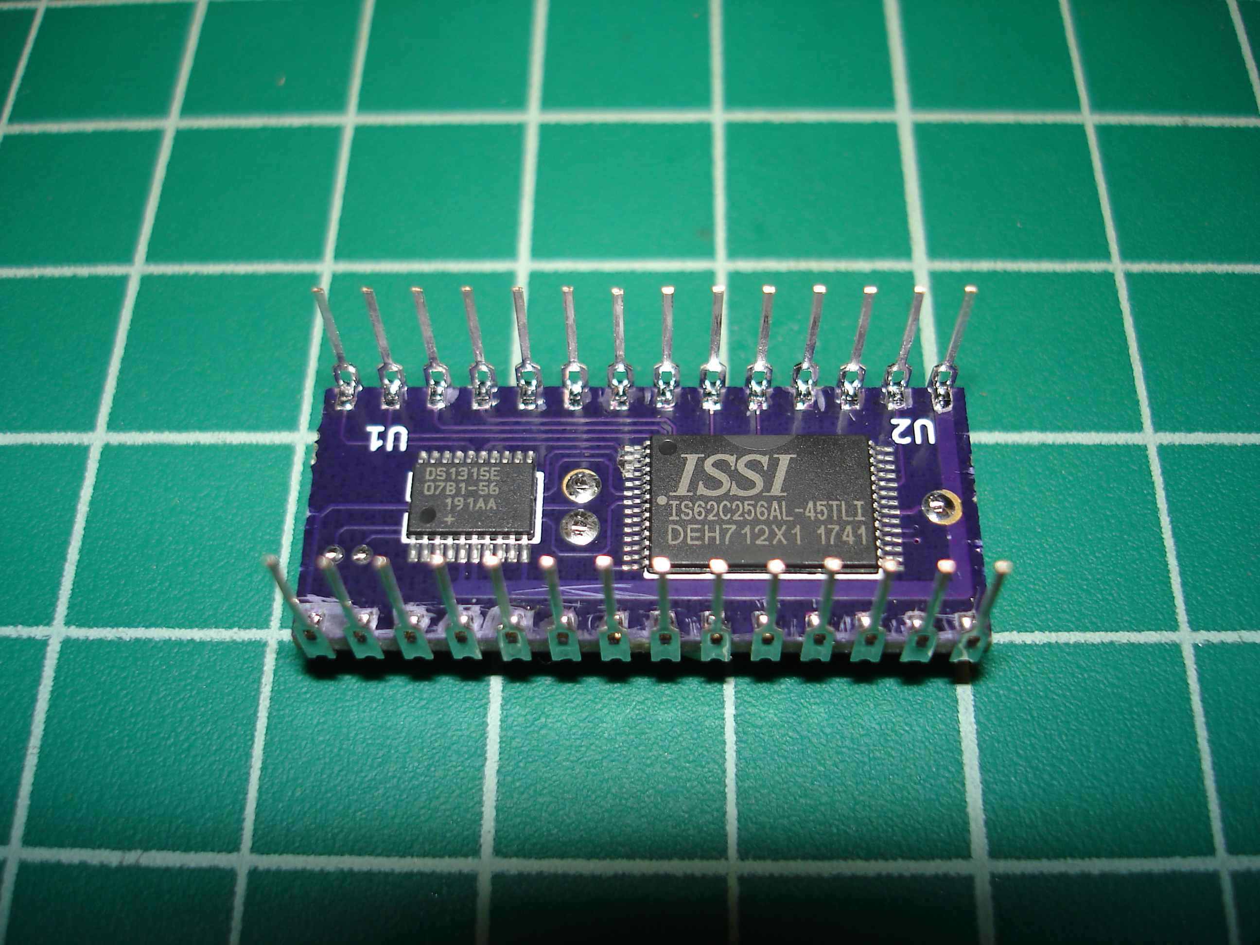
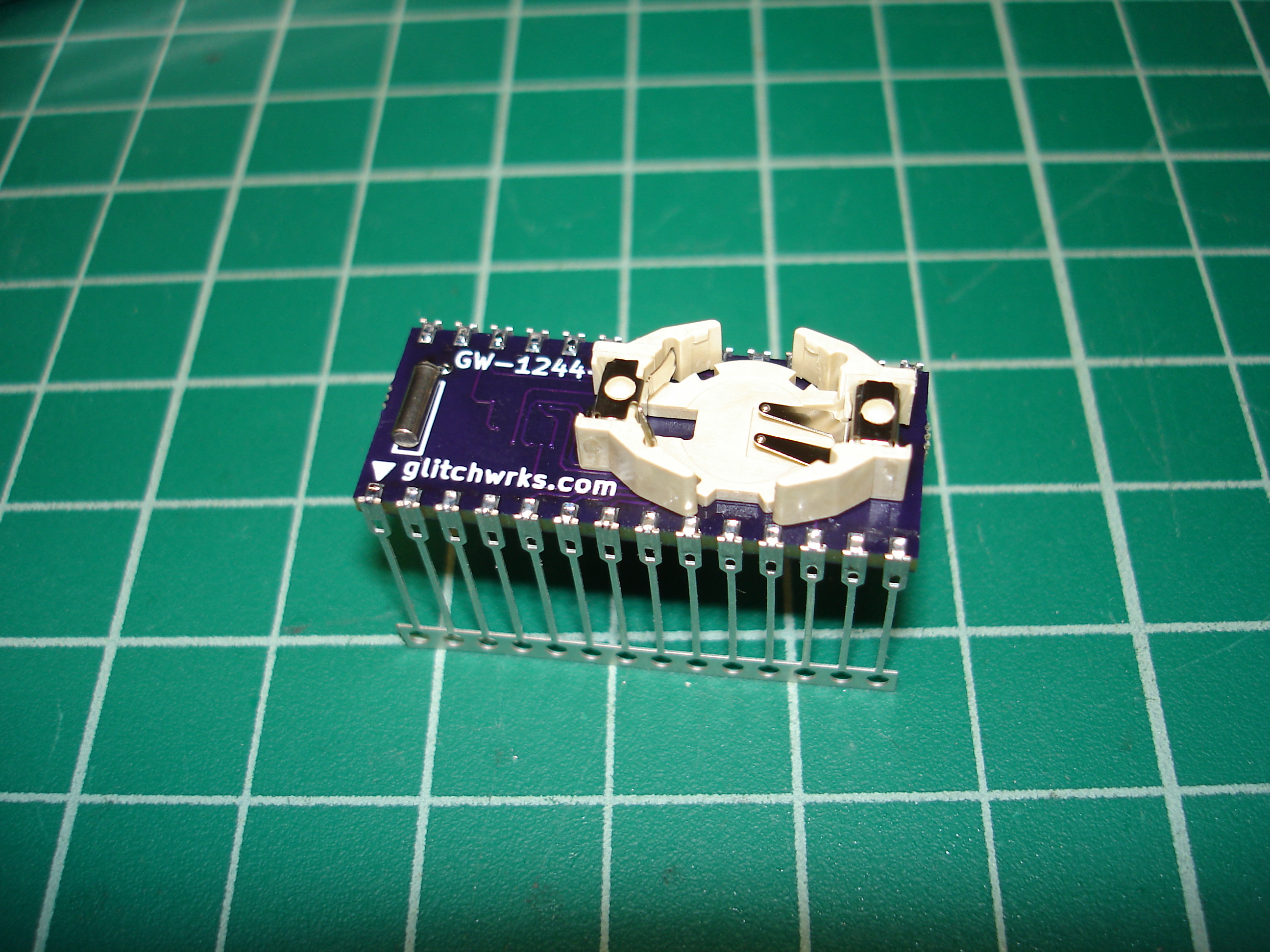
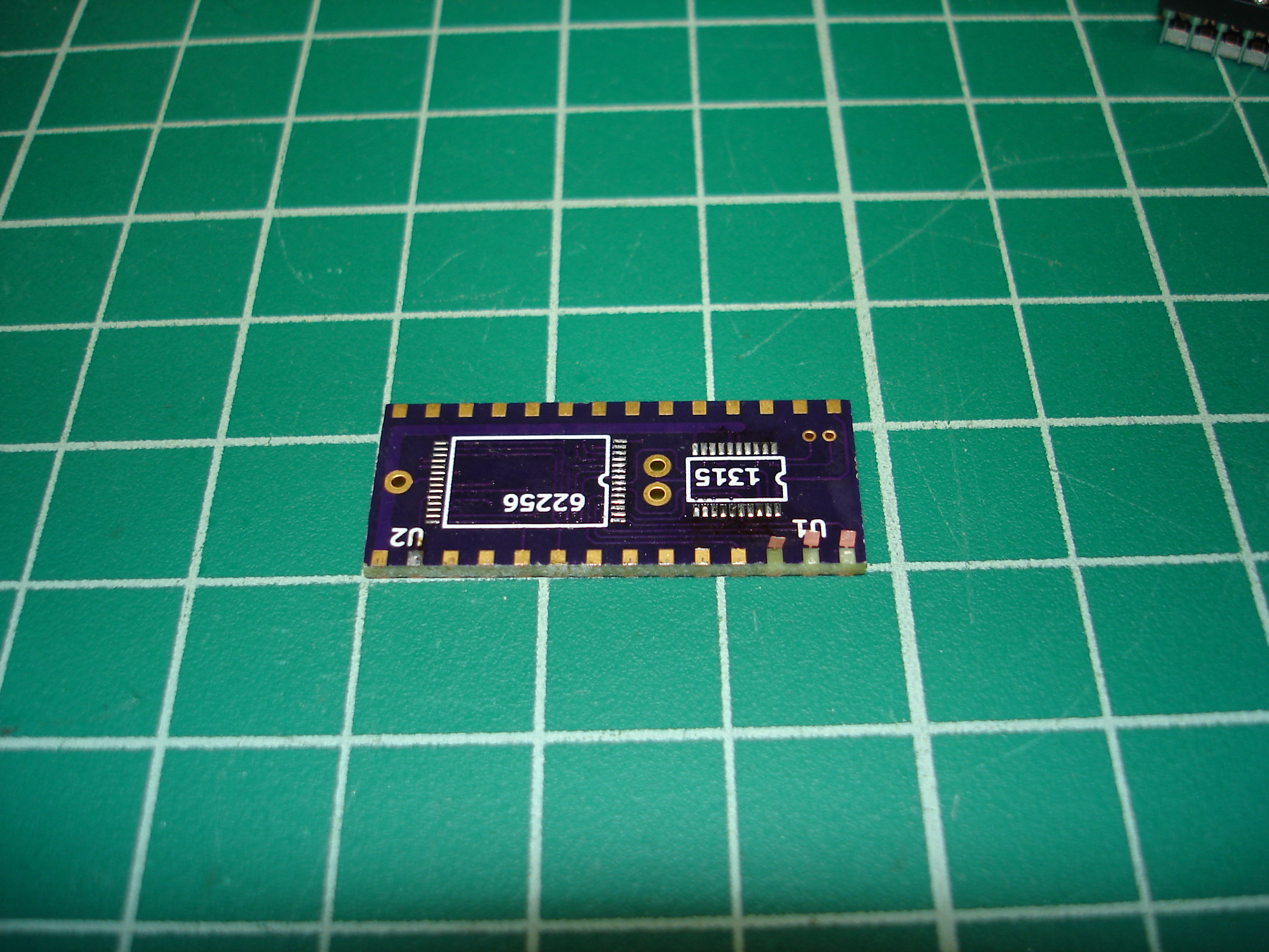
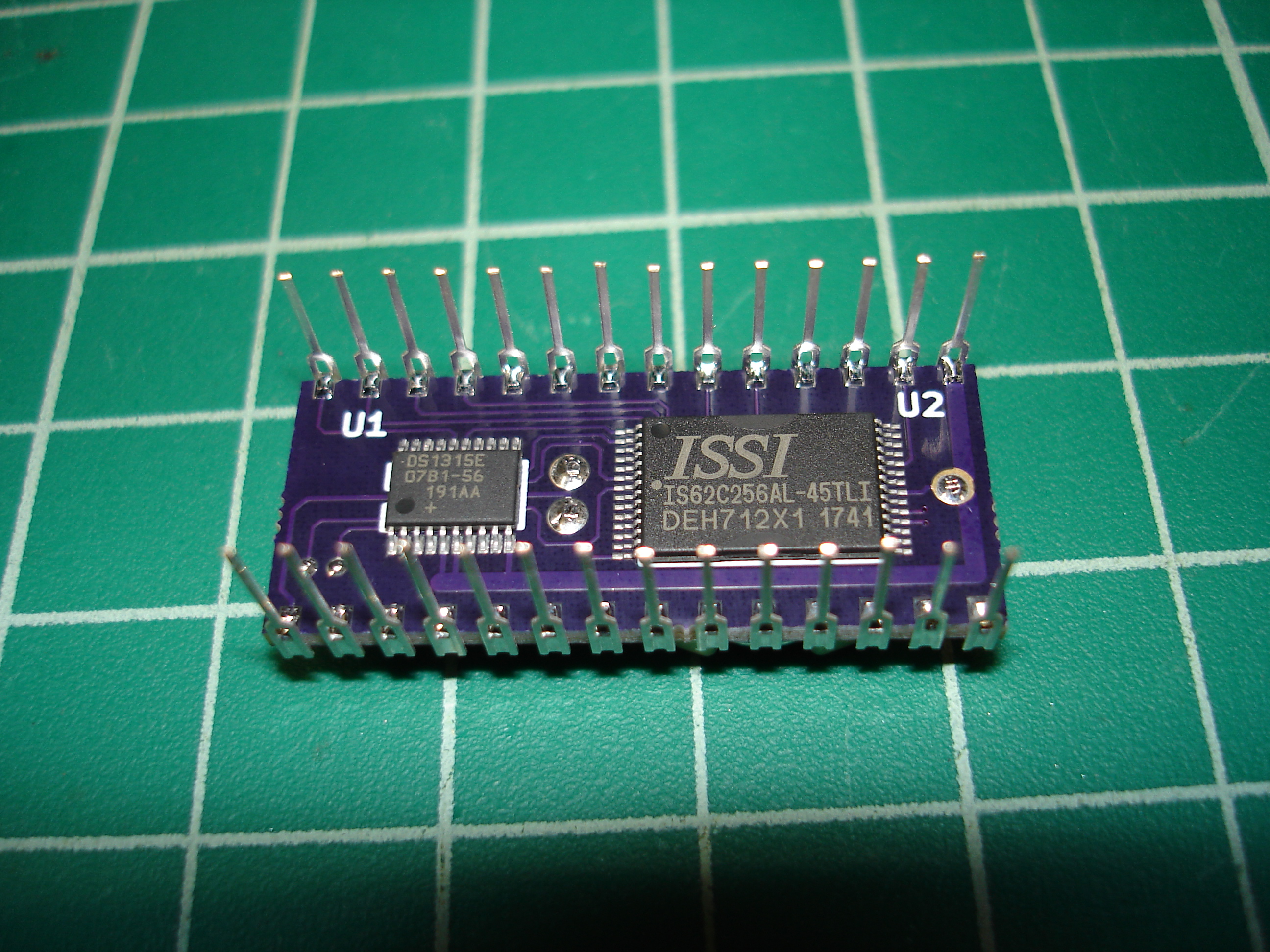
After tracing some of the connections on the original DS1244 module, it became clear that the DS1244 is just the datasheet reference implementation of the DS1315 with a static RAM. Aside from the physical size constraints, that fact made for an easy replacement design. This seemed like the perfect application for Batten & Allen DIP leadframe pins. I’d purchased some samples from D’Asaro Designs several years ago and used them in this project. The board was laid out in KiCad and samples run at OSH Park:
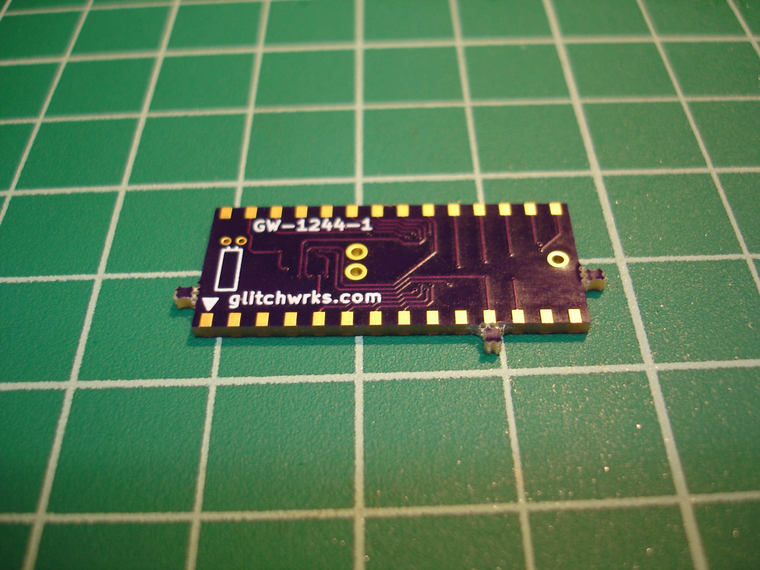
This is why you always run prototypes first! My footprint for the Batten & Allen pins lacked openings on the bottom solder mask! The solder mask was manually scraped away from the pads, and the board assembled.
Since the DS1244 is soldered in the DECbrouter 90T1, I didn’t want to test the prototype in the DECbrouter. The replacement module is JEDEC compatible and can be used in place of any JEDEC-compatible SRAM, so I tested it in my Ferroelectric RAM S-100 board prototype with the IMSAI:
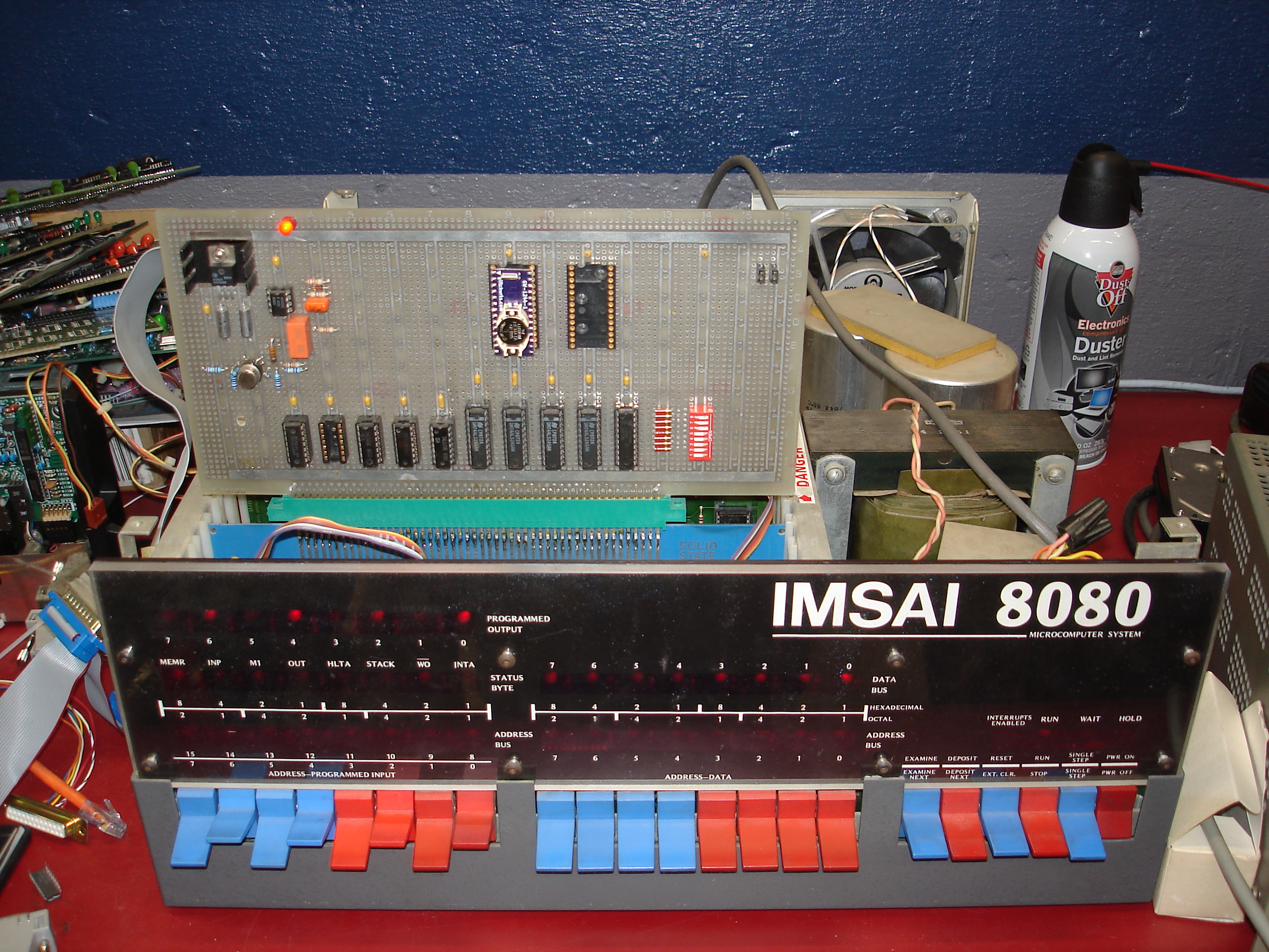
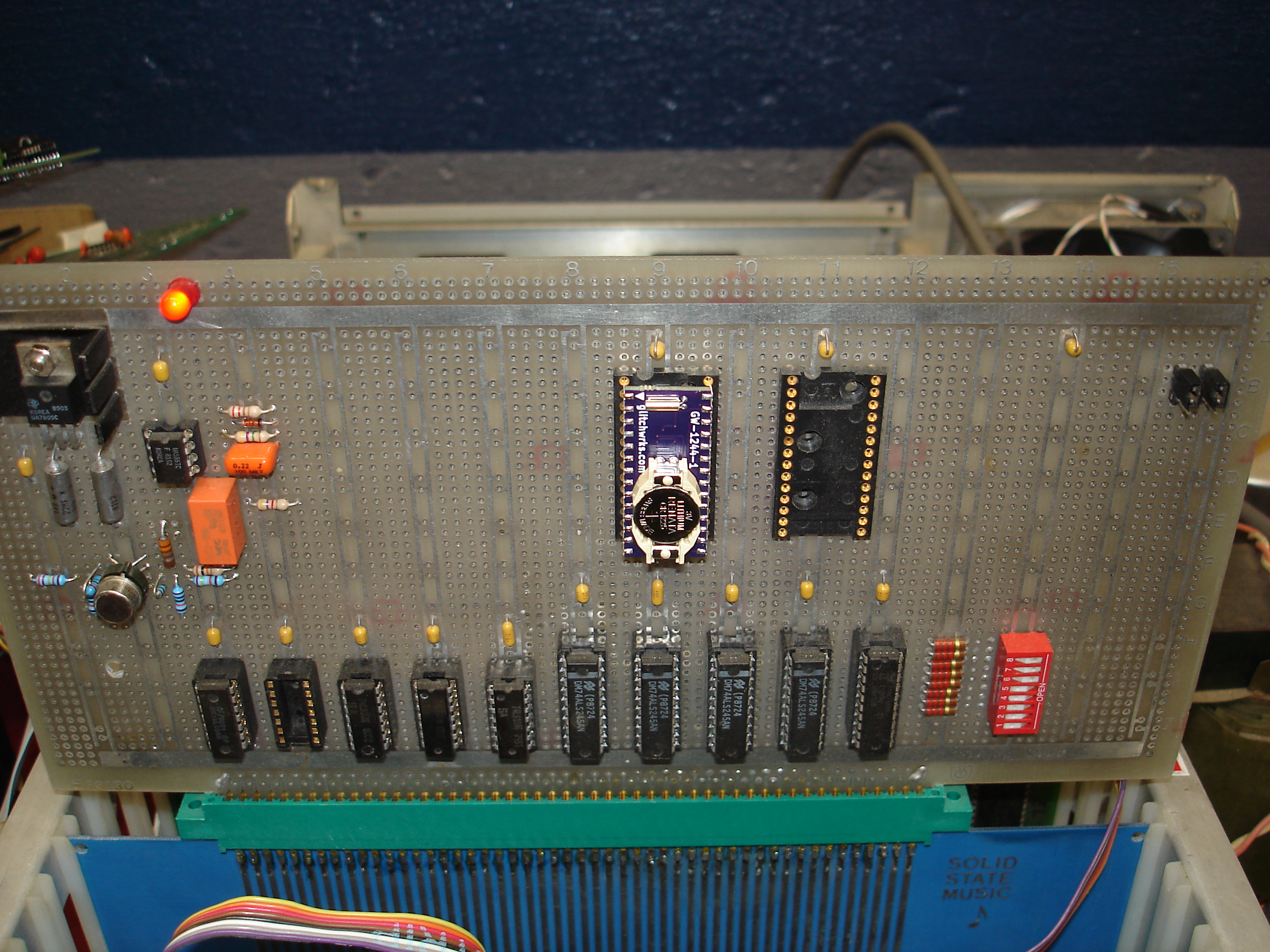
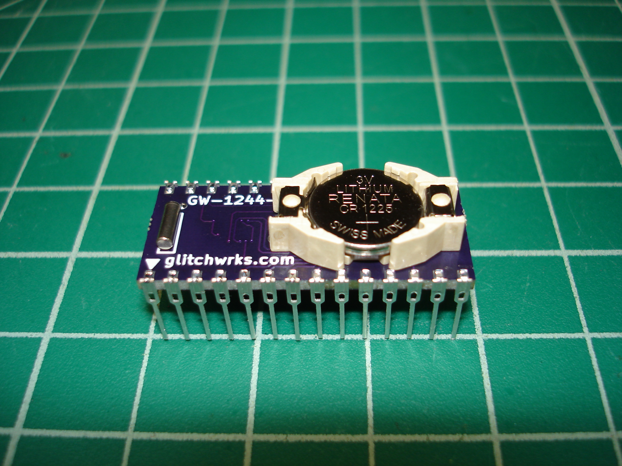
The prototype GW-1244-1 worked perfectly and retained data after a power-off! The Phantom RTC function was not tested in the IMSAI since the NVRAM test confirmed that the SRAM was properly connected and that the DS1315 was doing its job. The DS1244 was desoldered from the DECbrouter and the new module installed:
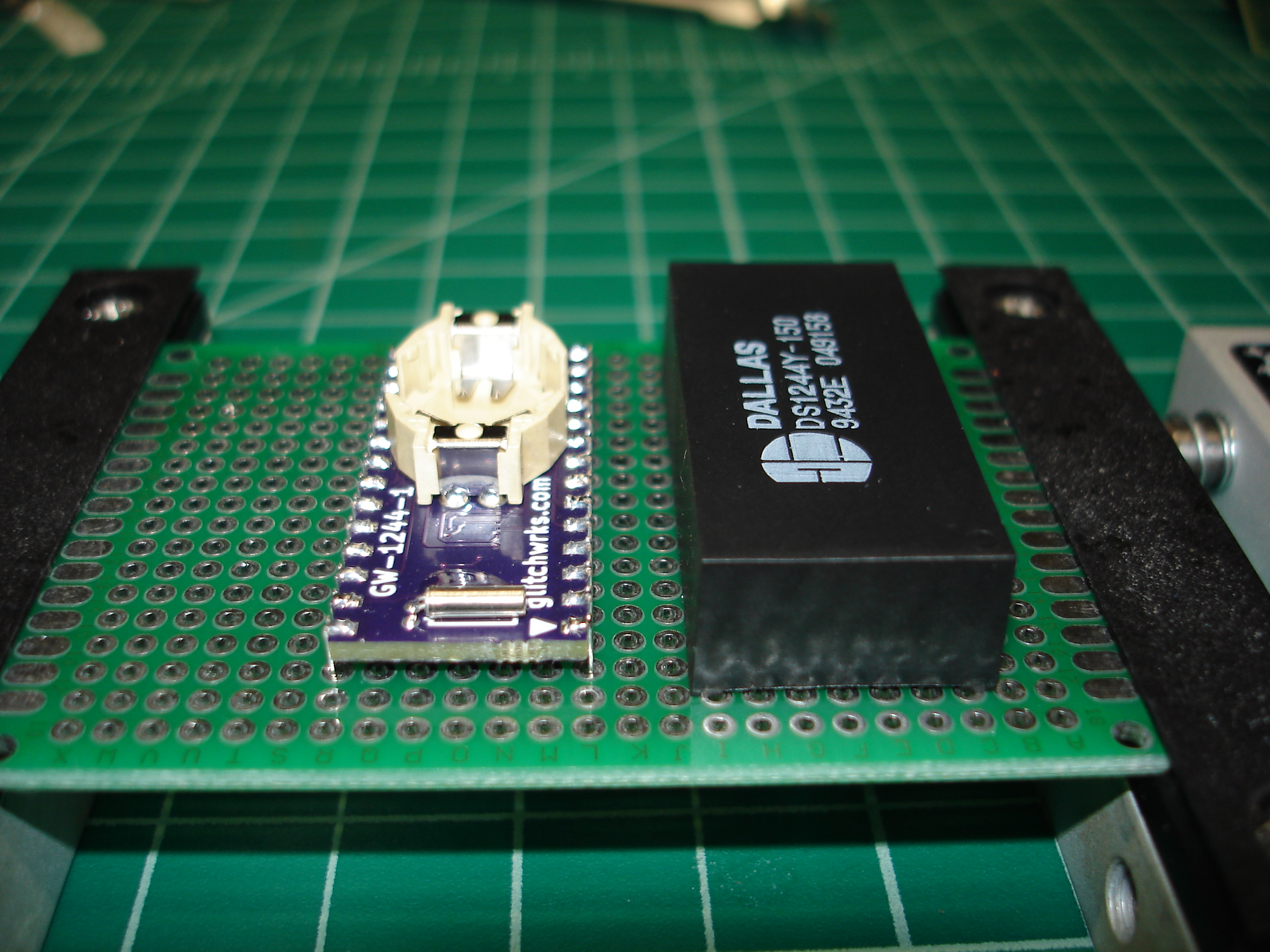
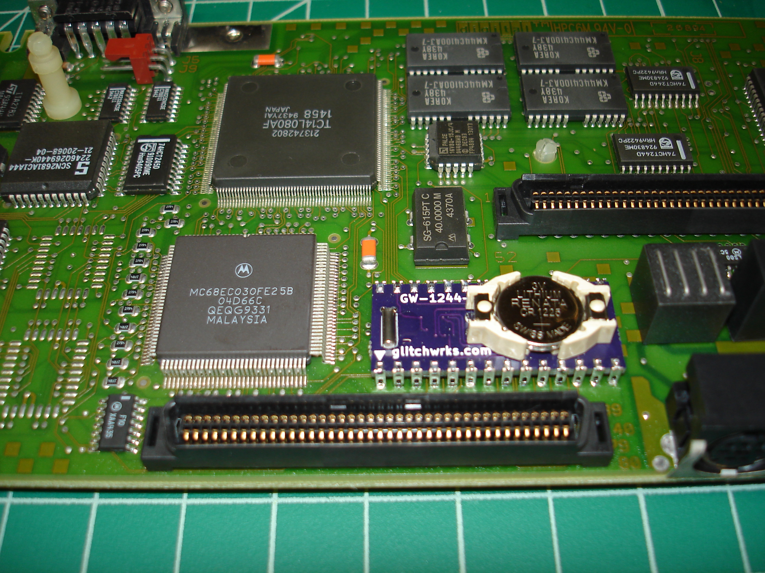
The GW-1244-1 is slightly shorter than the original DS1244, which is important as there’s a mezzanine above the NVRAM in the DECbrouter. The first prototype was a bit too wide, which is fine for installation in PC board holes, but was a little bit of a tight fit in a machine pin socket. That, and needing to confirm corrected solder mask, led to a second prototype run:
Unfortunately, some of the pads on the prototype lifted while putting the Batten & Allen leadframe on. Apparently OSH Park’s prototype boards have a little less copper adhesion than the production board house I use! No problem for a prototype, the ICs were recovered with a hot air rework tool.
A few small outline and silkscreen tweaks were proven out in the second prototype. The outline for the 32.768 KHz crystal was adjusted to match the actual crystal being used. The silkscreen outlines for the TSSOP ICs were adjusted to keep the silkscreen from being cut by the solder mask/copper keepout in production. The IC designations and values were also rotated to match orientation when the module is turned over.
NVRAMs replaced