Topic: Adding slot 8 support to the XT-IDE rev 2
Date: 2017 FEB 05
Quick Links
- GitHub Repository
- Build Thread on VC Forums
- XT-IDE rev 3 Installation Writeup
- Slot 8 Support on Glitch Works Tindie Store
Part of the purpose in doing XT-IDE Slot 8 Support as a daughterboard module was to make Slot 8 Support available for older revisions of the XT-IDE board. It’s usable on any previous board that has ISA pin B8 present on the edge connector. Many of the rev 1 production run boards had this pin removed to save on plating costs, so the Slot 8 Support board won’t work there. It does, however, work with the XT-IDE rev 2 boards, and allows use of ROM, IDE, and even the onboard serial port when the board is installed in Slot 8.
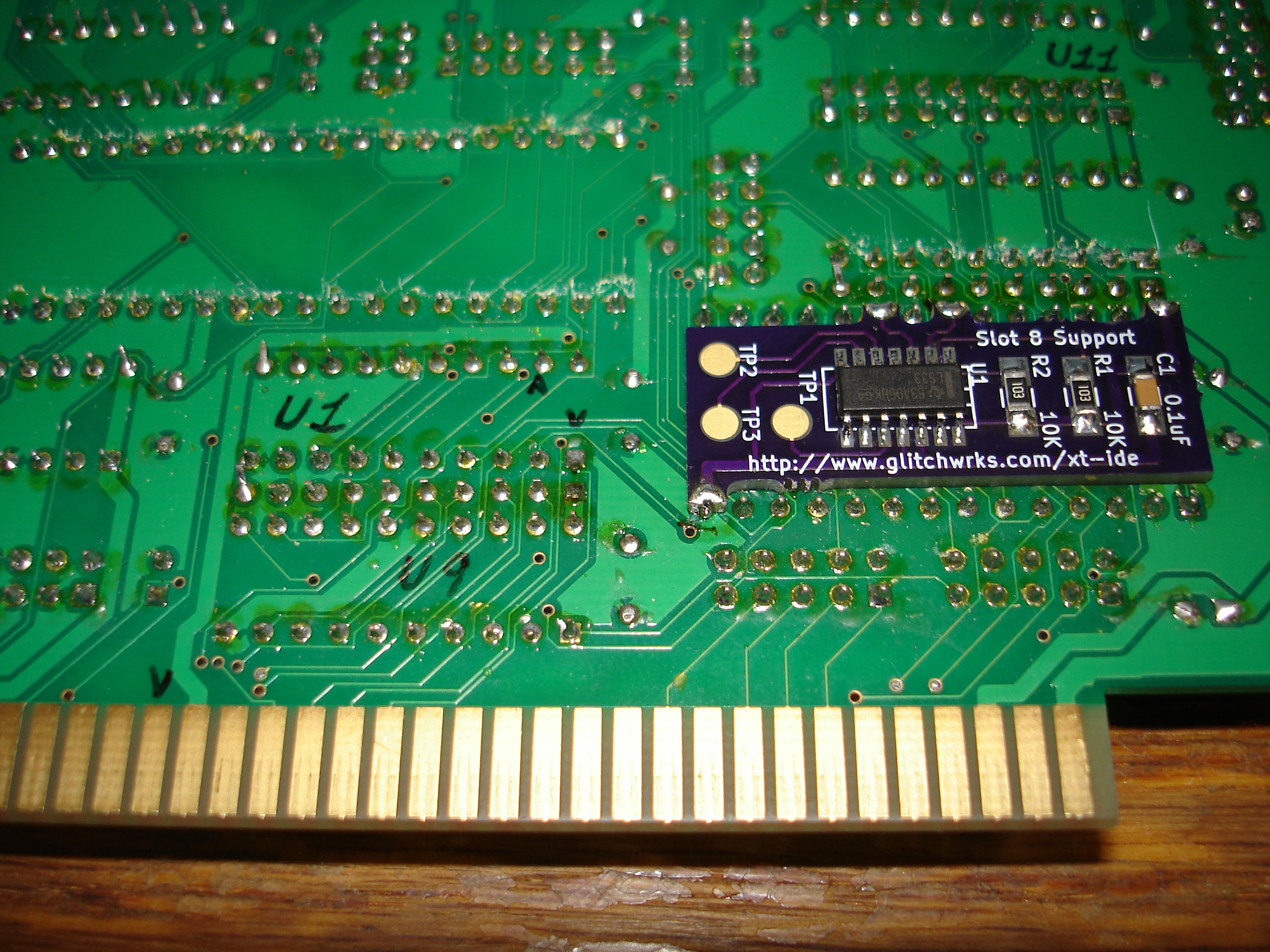
For this installation, I used an earlier prototype from OSH Park – this one uses silkscreen, which was removed in a later revision to allow the board to be produced for less. I went ahead and labeled a few of the ICs on my XT-IDE rev 2 board, and marked the pins we’d be soldering to with small arrows. I used a permanent marker, which will usually erase from the board with isopropyl alcohol.
Installation is the same basic process as with the XT-IDE rev 3: start by removing the solder from pins 14, 20, 22, and 28 of the EEPROM. You only need to remove solder so that the pad is flat, it’s not necessary to remove it from the through-hole. Orient the Slot 8 Support module with the capacitor toward the IDE connector end of the XT-IDE. Mount the Slot 8 Support module using its four tabs, soldering them down and keeping the Slot 8 Support module as close to the XT-IDE circuit board as possible:
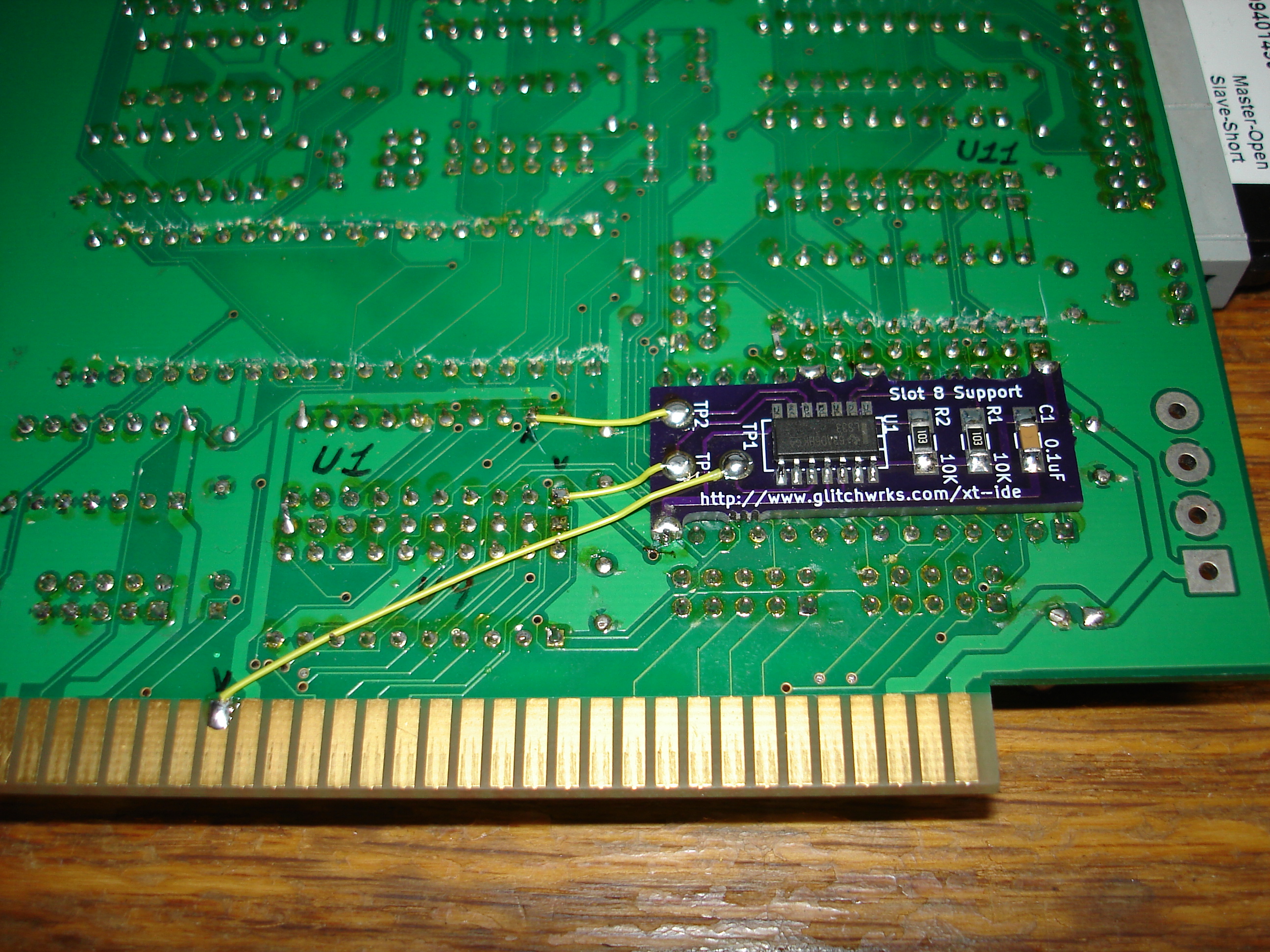
Since there are no spare jumper or switch positions on the XT-IDE rev 2, I initially installed the module permanently, with no way to disable Slot 8 Support:
Hacking in Jumperable Slot 8 Support
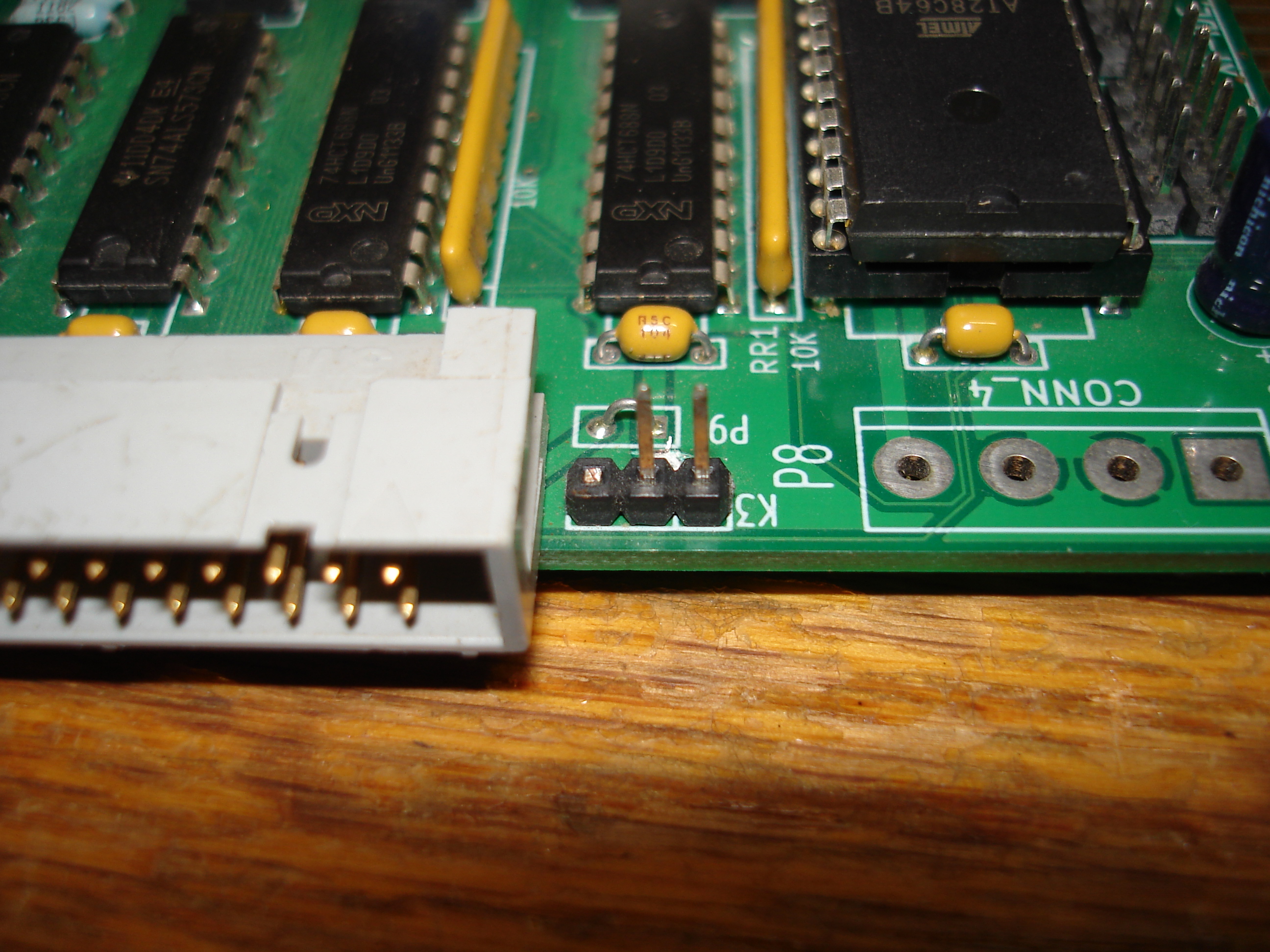
One of the VCForums members requested a way to disable Slot 8 on rev 2 boards, so I came up with the following hack. Jumper K3 on the XT-IDE rev 2 supplies +5V and GND through a three-pin, 0.1” spaced header near the IDE connector. I’m not sure what, if anything, actually uses this feature. Here’s K3 on a bare rev 2 board:
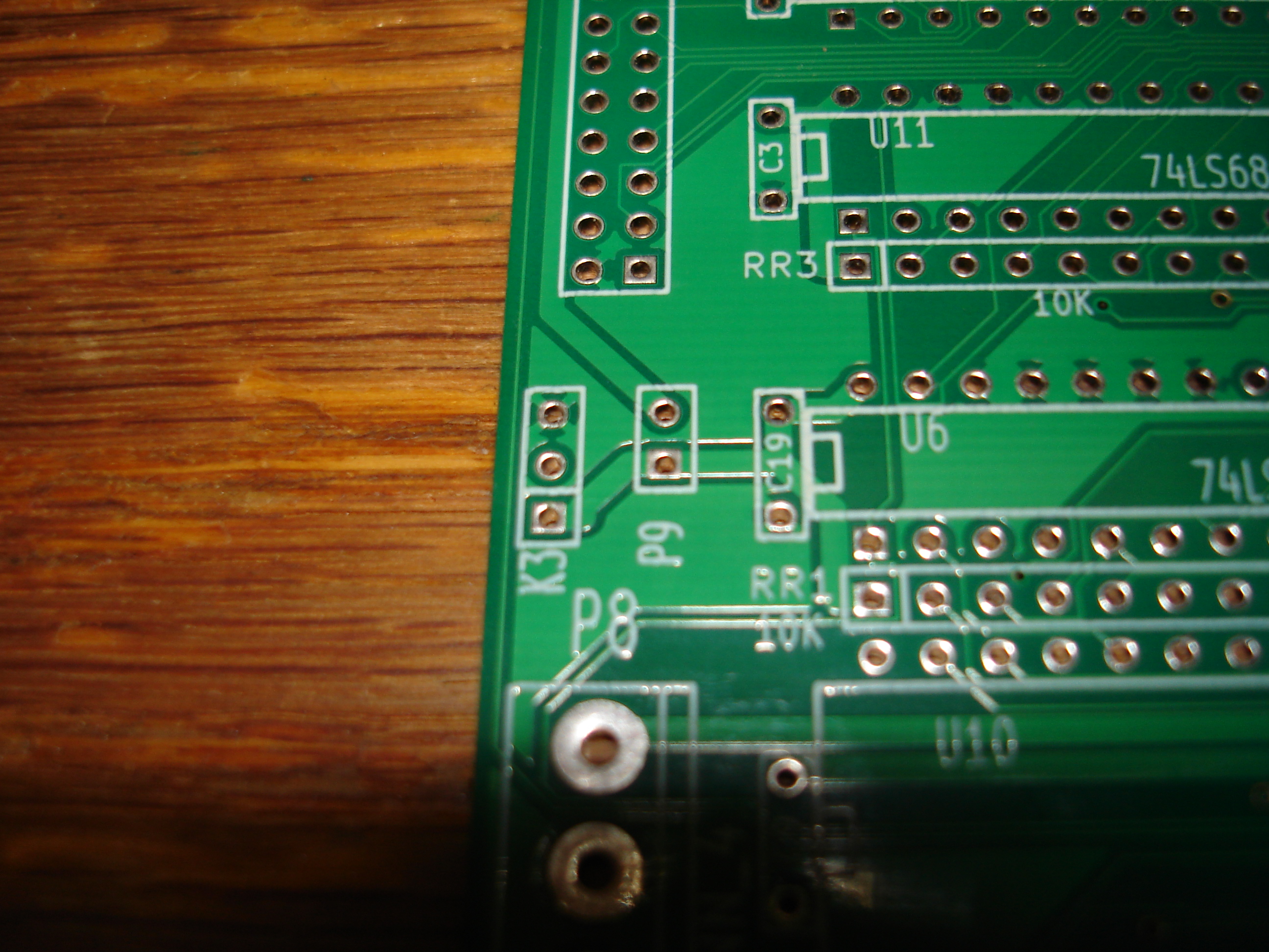
Since this is the end of the line for the +5V trace that goes to K3, and the center pin is left unconnected, we can repurpose K3 as a Slot 8 Support enable/disable jumper. Start by cutting the +5V trace on the component side of the XT-IDE, between K3 and P9:
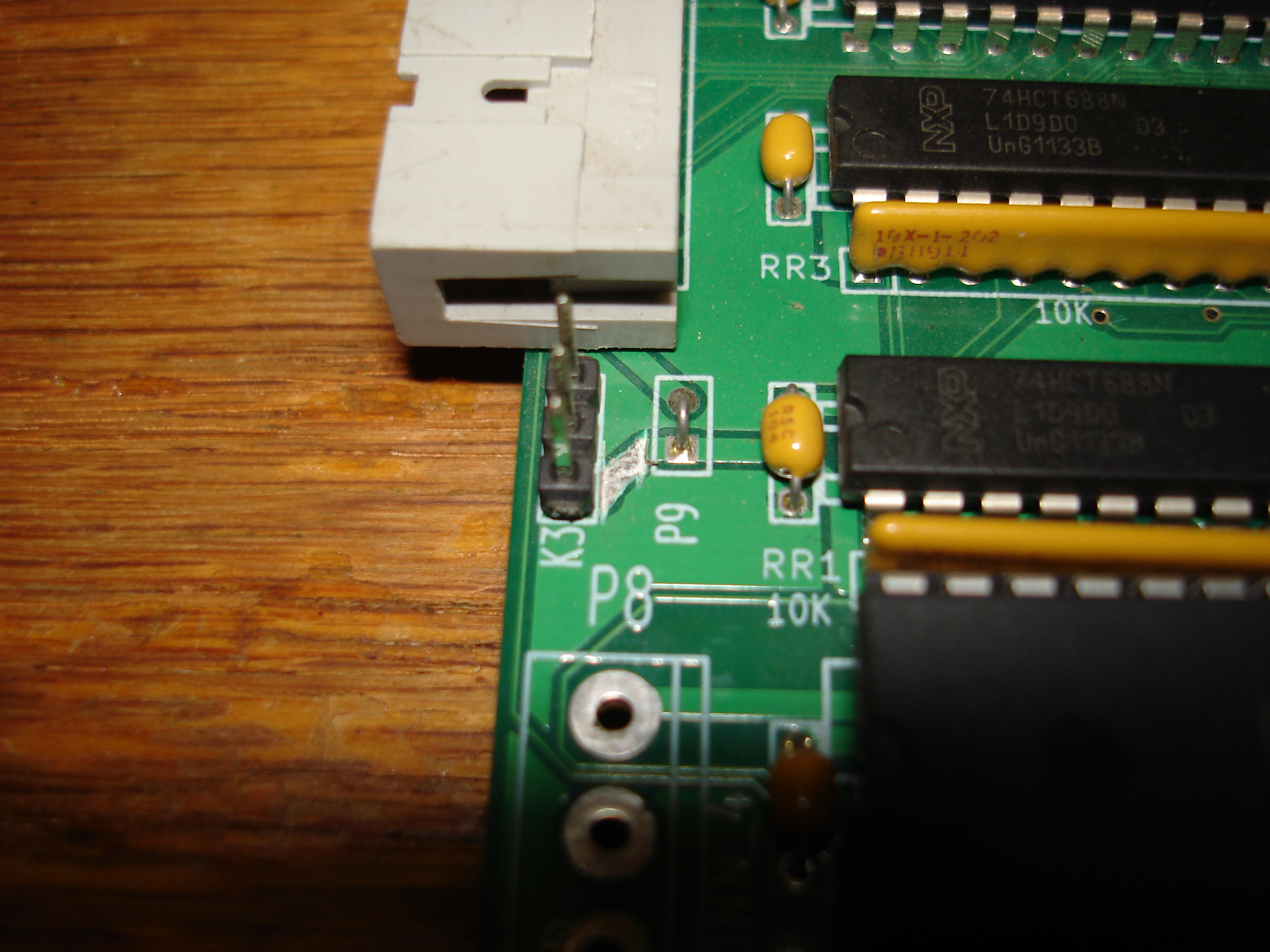
As you can see, I like to remove a lot of trace when I make a cut! With the trace cut, snip off the uppermost pin of K3, the pin nearest the IDE connector:
Route TP1 from the Slot 8 Support module through the remaining two pins of K3, and down to ISA pin B8:

That’s it! If you performed the K3 modification, put a jumper shunt on K3 to enable Slot 8 support, and remove it for use in regular slots. If you’re interested in ordering a bare board, parts kit, or assembled module, please use the contact form to make your order. If you have an XT-IDE rev 3 card, here’s the installation writeup.
XT Slot 8s Utilized