Topic: Building a rack-mounted DC power supply to eliminate wall warts
Date: 2016 JAN 03
I’ve got a few rack mounted items that require DC power instead of AC, and the factory solution for this is usually a wall wart or power brick. I especially don’t like using wall warts as they usually cost two receptacles and seem to be prone to unplugging themselves over time. Over the Christmas/New Year’s holiday, I decided to finally build a DC supply for the rack, and start eliminating individual power supplies.
As luck would have it, I acquired an excellent enclosure to repurpose for the project: a large, heavy, linear supply from some piece of lab gear. It came with a group of unrelated lab gear so it was effectively free. While still functional, the linear design is inefficient and couldn’t supply enough power per connector for my needs. The aluminum chassis and especially the front panel seemed like the perfect thing to hack into a centralized DC supply for the rack.
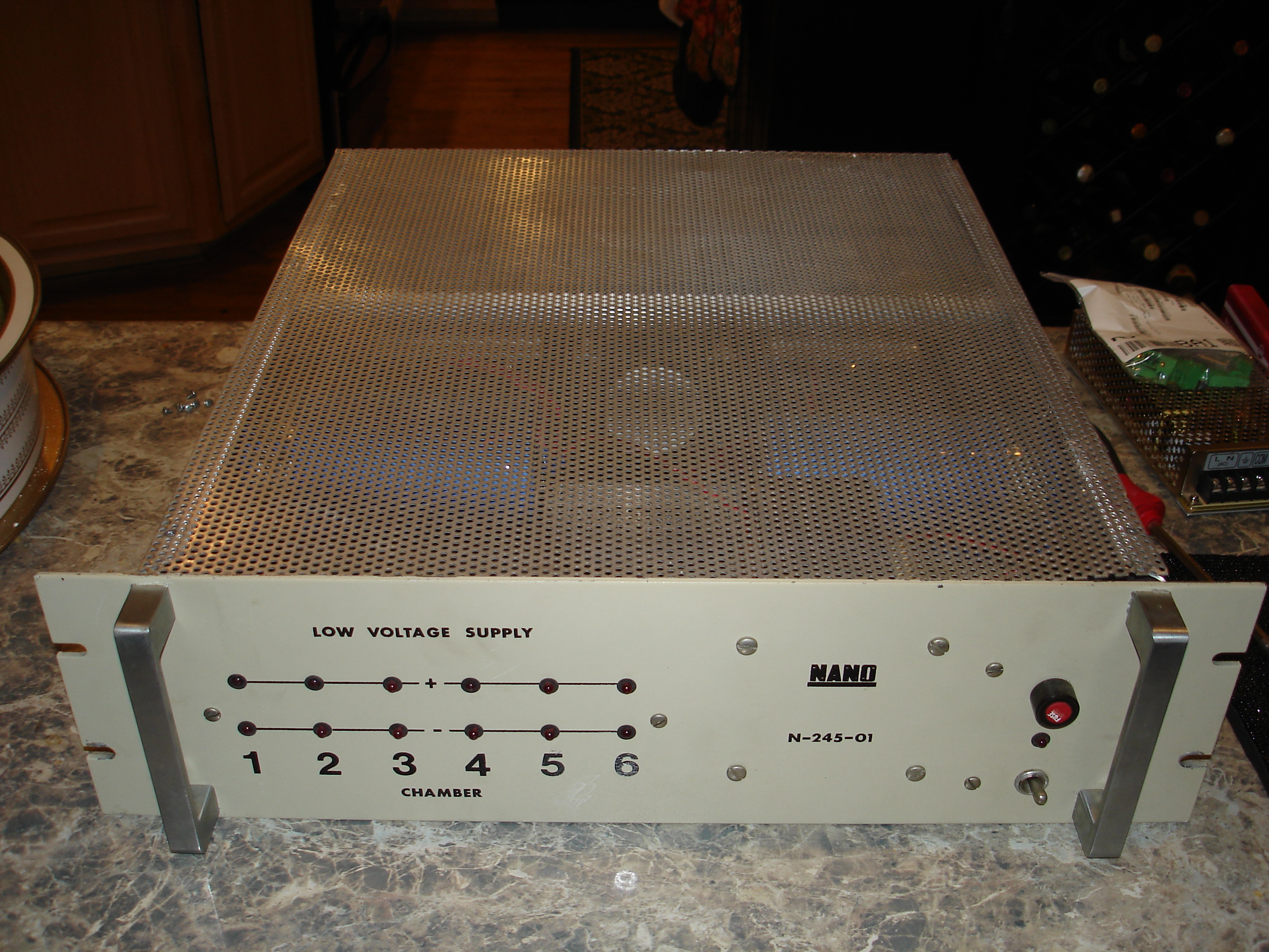
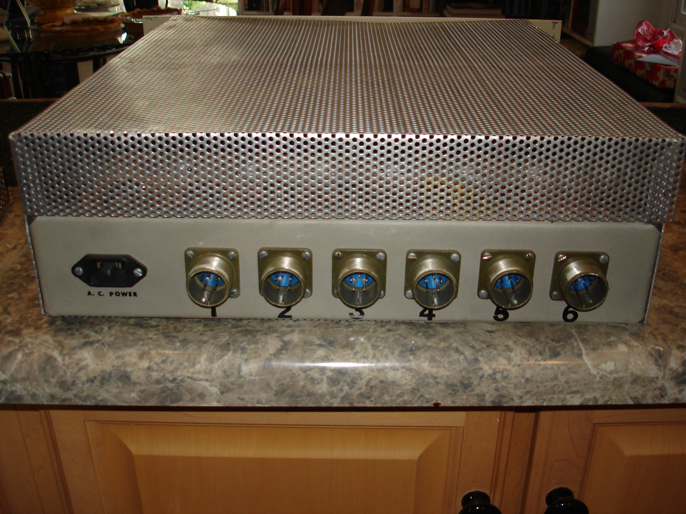
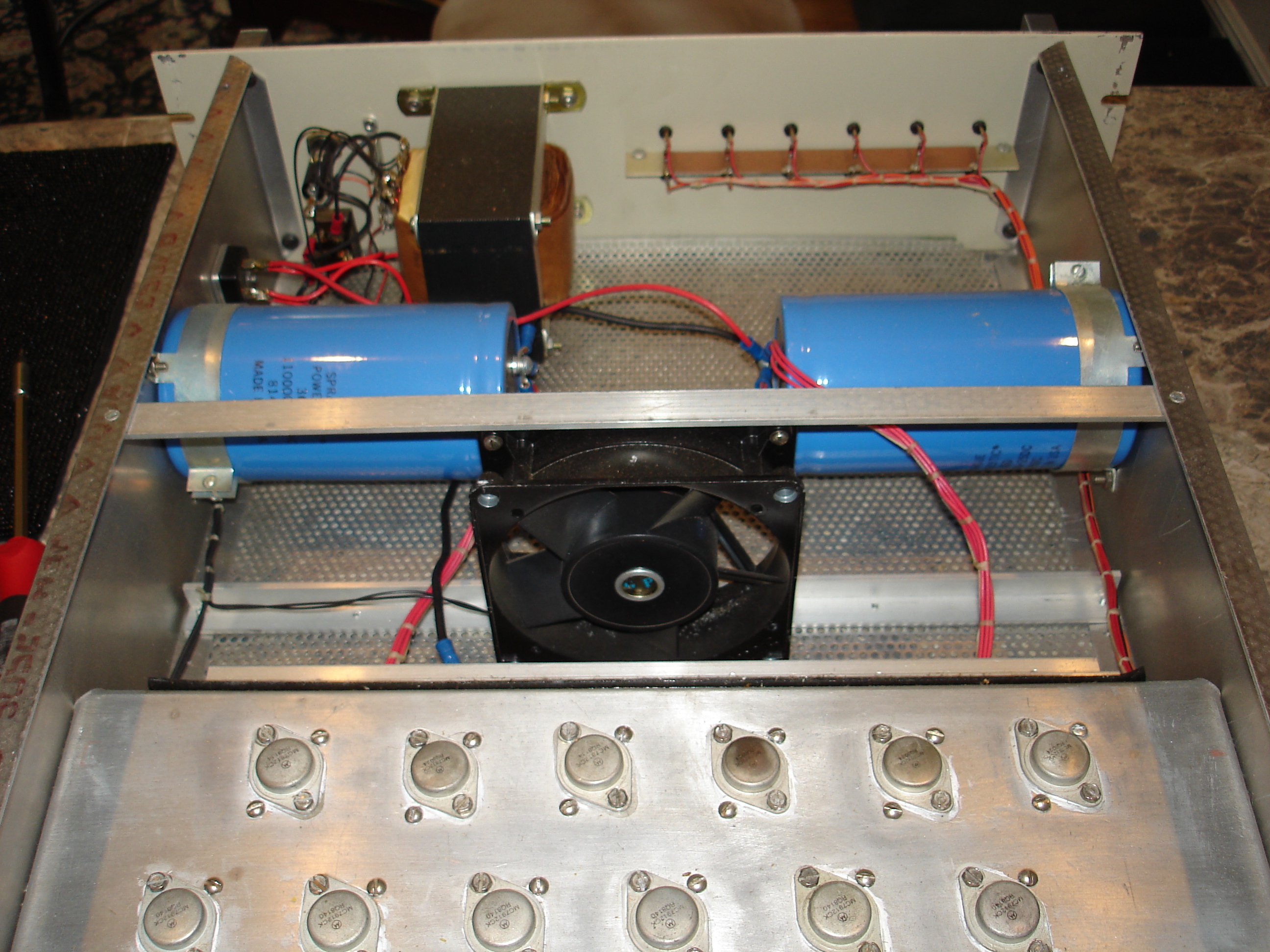
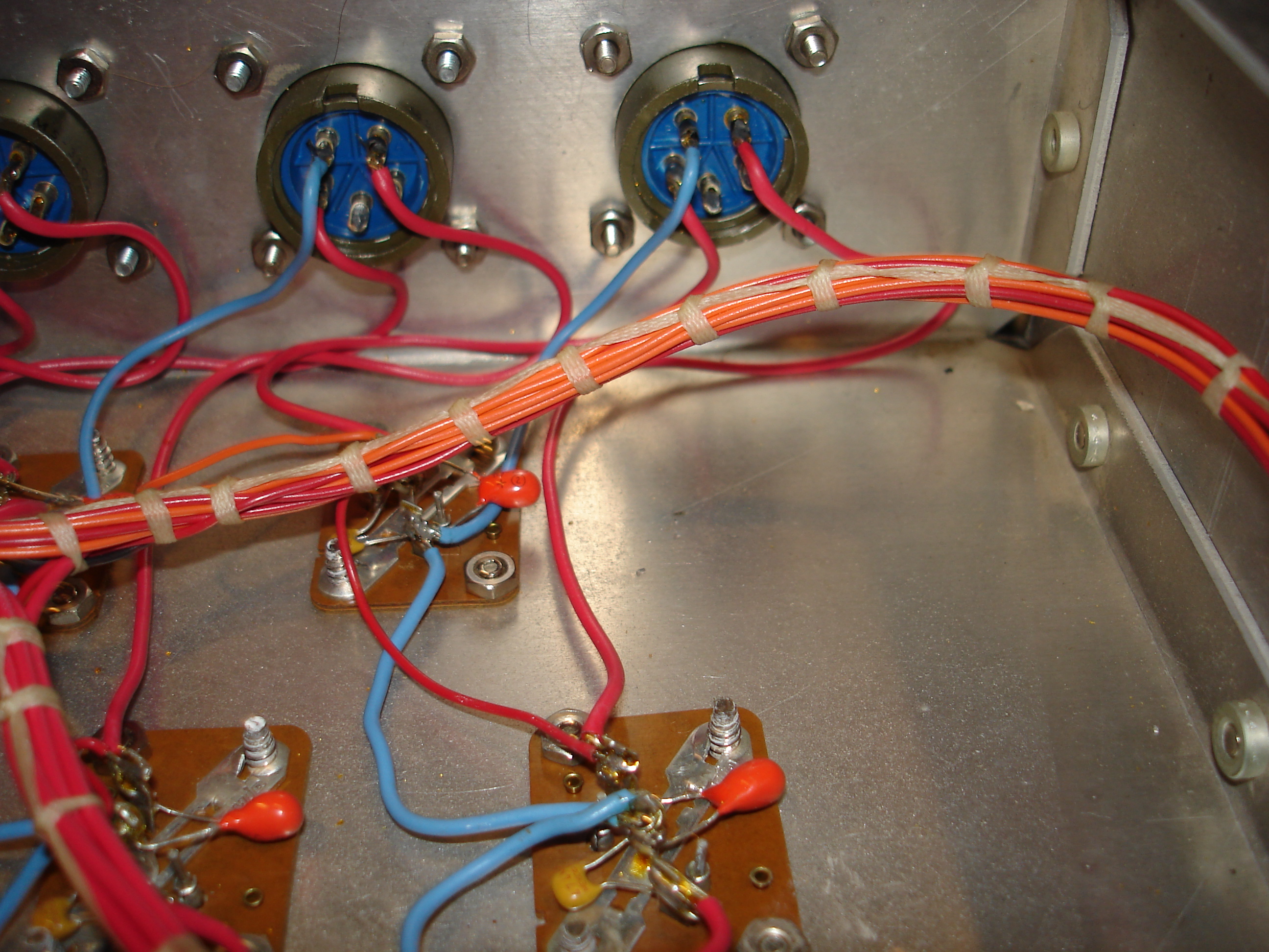
The original supply was a pretty basic linear arrangement: bridge rectifier, two massive filter capacitors, and several linear regulators. This unit provided six bipolar 12V supplies through military-style Amphenol connectors. The circuit was all point-to-point. Construction of not only the circuitry but also the enclosure itself seems to have been done by hand. All small wires were neatly laced into cables using flat, waxed lacing tape:
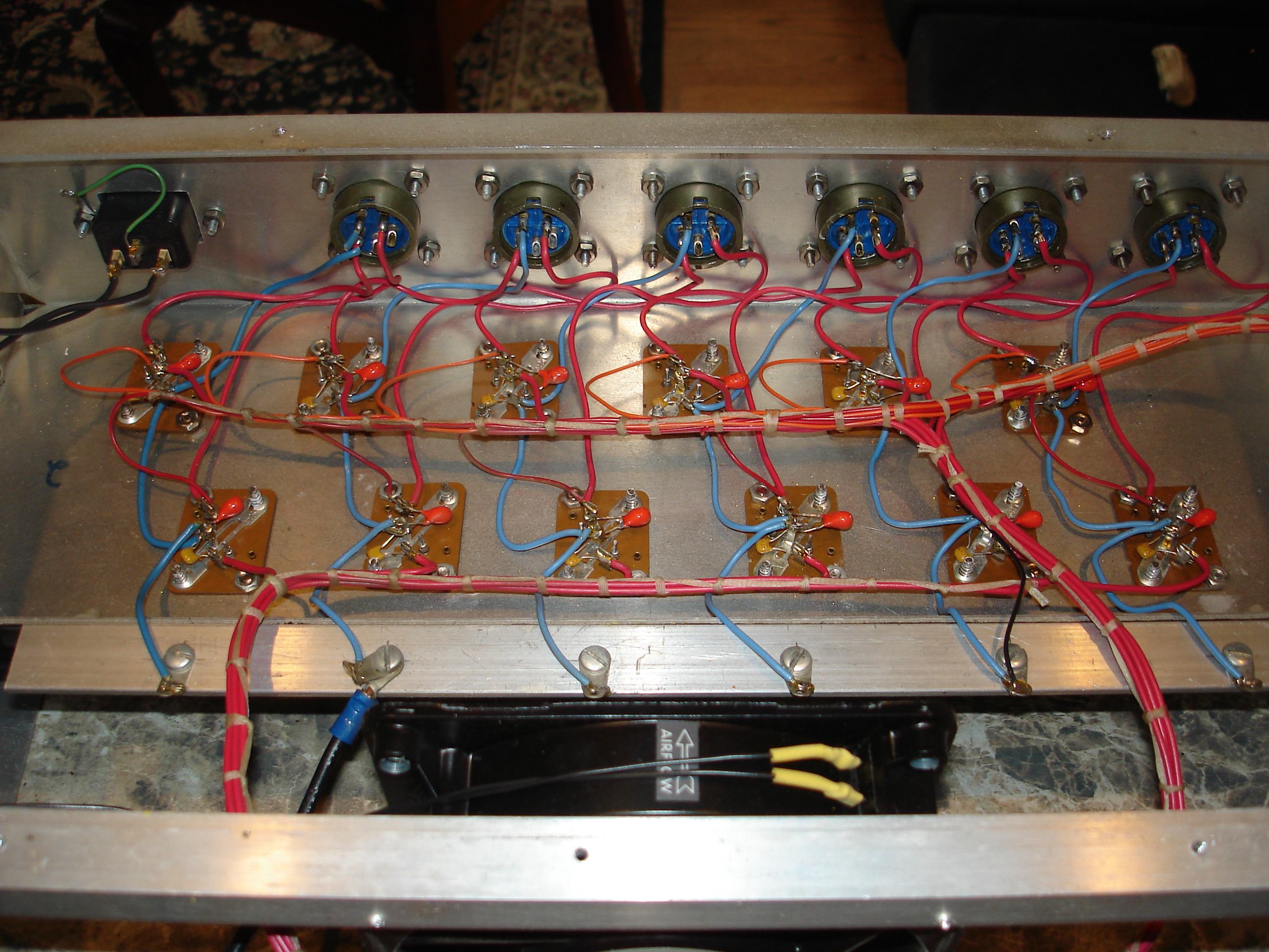
Here’s a closeup of the wire lacing near the power regulators:
The construction of the supply sort of dates it. It uses a large Stancor transformer, carbon composition resistors, and pretty early LEDs. The LEDs are similar to a believed-HP part featured in the 1970’s section of the LED Museum, most of the way down the page. I’m not sure if the black collar is metal or plastic, but it looks as if it was inserted into the mold, then filled with red epoxy. Not sure why this was necessary, but they still work!
![["Old LEDs"]](/~glitch/images/hardware/rack_dc_supply/old_leds.jpg)
Aside from the inconvenience of wall warts with rack power strips, I don’t care for barrel plugs in situations where the power cord will be hanging at a right angle to the equipment. Plus, the barrel socket in the equipment always seems to be a different size from the plugs available on the power supplies I have! As such, they’re getting replaced with pluggable terminal blocks, or “Euro connectors.” These seem to be almost always cast from a light green plastic. The sockets are available in several board and panel mount styles, and plugs are available as solder, crimp-on, or screw termination. Here’s the plug portion that gets mounted on the power supply:
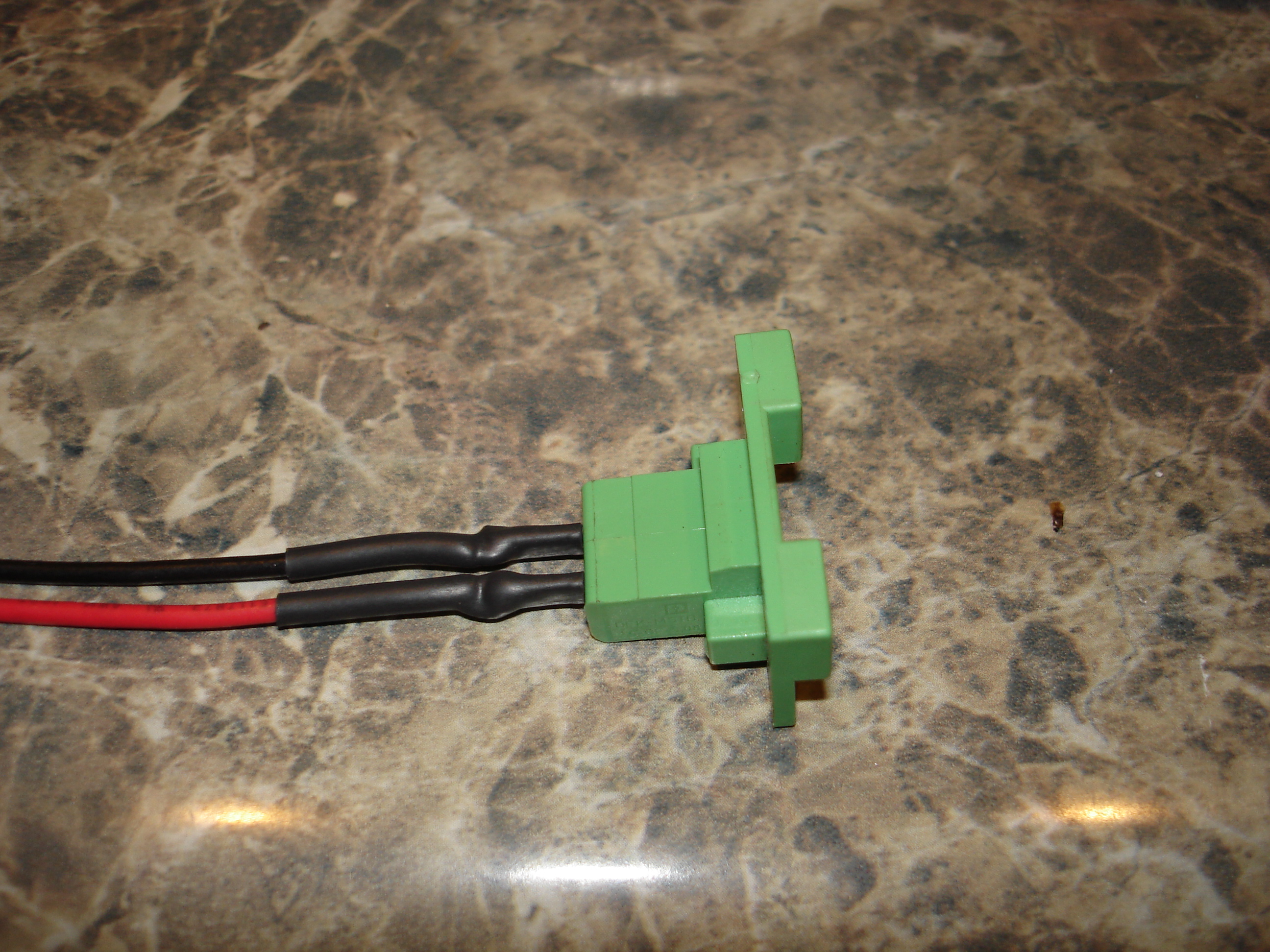
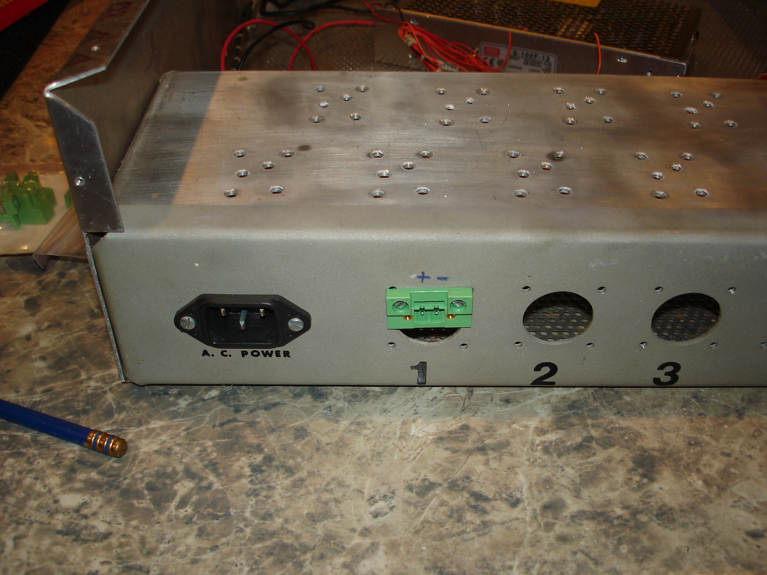
This particular jack is Phoenix Contact part # 0710170 and is available through the usual sources – mine came from Mouser. A similar jack gets mounted in the gear that requires DC power, replacing the original barrel connector. These connectors latch, which makes them less likely to fall out. I keep a few of the screw terminal plugs in my parts box for running DC-powered equipment outside of the rack and away from the central DC supply.
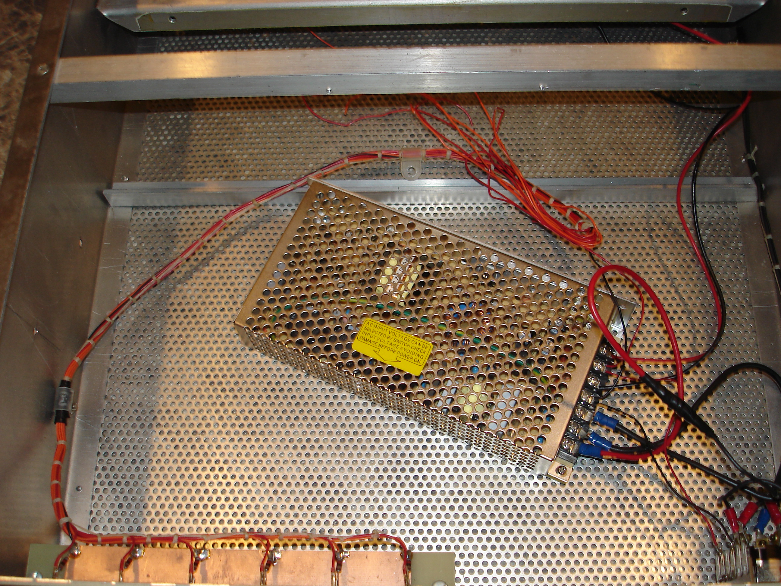
With the old linear components gutted (don’t worry, they’ll get reused!) and the first DC jack installed, it was time to install the new switchmode supply. This project will eventually supply 24V and 48V DC, and will eventually include network controlled power relays for each jack and load monitoring, but for now it’s just a box with a modular switchmode supply in it. I chose a cheap, used Mean-Well 8.5A @ 12V DC that needed recapped before use. Since this isn’t the permanent arrangement for this supply, and I just needed to get it up and going, I aligned the tapped mounting holes on the Mean-Well supply with the holes in the mesh bottom of the enclosure and secured it:
Currently the switchmode supply is wired directly to the AC switch and fuse. Its output goes to the DC jack, the first positive power indicator on the front panel, and the “AC ON” indicator on the front panel. I left the front panel wires loomed for now. Here’s a picture of the finished (for now) project, racked under an APC PDU and powering the OpenBSD perimeter router/firewall:
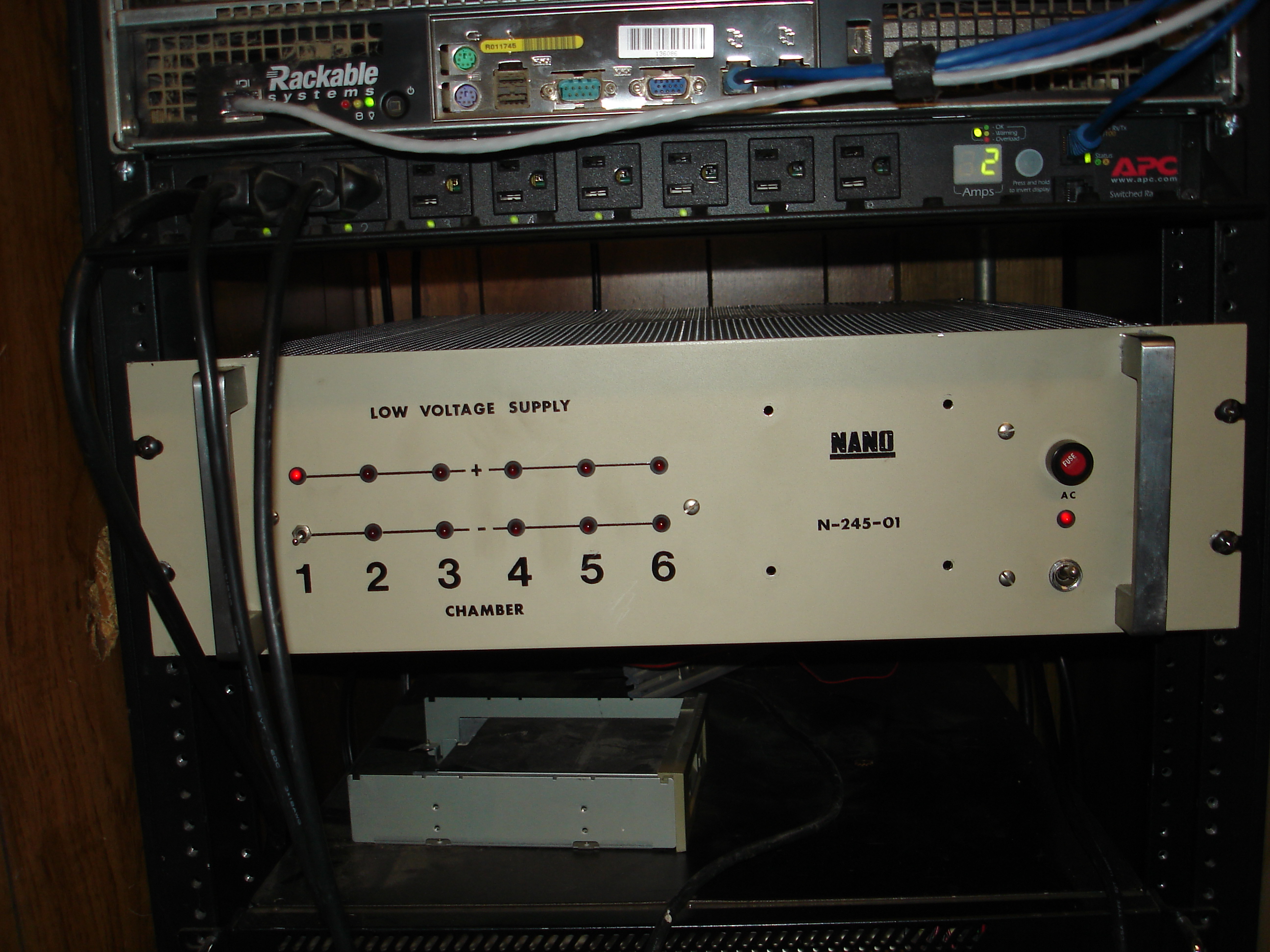
wall warts replaced