Topic: Controlling relays with 24V coils
Date: 2013 FEB 28
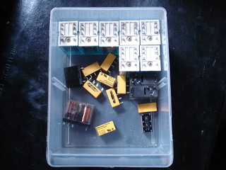
I’ve got a lot of relays in the parts bin with 24V coils. This is a common control voltage in industrial and telecommunications equipment, so the relays are common in surplus equipment. Many will actuate equally well on AC or DC, which makes them an easy solution when the control voltage is switched mechancially, as in the case of limit switches or magnetic reed switch sensors. Unfortunately, they’re not so simple to interface directly to microcontrollers as they require a separate supply and level shifting circuitry.
Even so, one can easily control them with a separate supply and optoisolator. An optoisolator uses the illumination of a (mostly infared) LED to trigger a photosenitive resistor or transistor. This provides galvanic isolation between the control circuit and the device being switched, which also means that the power supplies don’t have to be the same voltage, or even share a common ground. Additionally, transistor-type optoisolators in DIP packages are extremely common and cheaply available if you don’t have a few in the parts bin. They also provide an easy method to control devices using a current loop. Using a current loop and a control current rather than a control voltage makes interfacing with a wide range of control voltages easy.

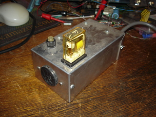
I came across a few things that made this project possible and/or necessary. First, I had a large supply of 24V relays sitting around. Second, I had a few trays of Prem board-mount transformers with dual primaries (120/240 VAC operation) and dual secondaries that could be series-wired for 24 VAC output. Finally, I came across a bunch of 24V coil relays that could handle 5 Amps @ 125 VAC and came with sockets that could be board or panel mounted. I used one of them and a point-to-point controller in this relay-controlled receptacle project:
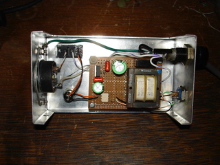
The controller worked fine and could be driven by 3.3/5/12 Volt control circuits without modification, since the controller included only a protection resistor and relied on an external current-limiting resistor. Driving the optoisolator’s source is literally as simple as driving an LED. The onboard Prem transformer has high enough rectified output to require a regulator, but still made for a fairly compact combined supply and control board. Small enough to be integrated into existing line-operated devices. A few friends were interested in control boards, so I decided to lay out a proper PCB and have a few produced. This would make the device a bit smaller and reduce assembly time.

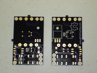
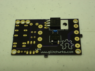
I laid out the board during my personal project time at work and sent it off to be fabricated. This was the first board to go off to the service that evolved from the DorkbotPDX prototype PC board service, OSH Park. The price is the same, and the quality is every bit as good. 12 days later, I had nine 2.15” x 1.35” boards that cost around $4.95 USD each:
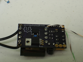
In an effort to make the boards smaller (and cheaper!), some components were placed on the bottom of the board under the power transformer. The bridge rectifier, 24V regulator, and a decoupling capacitor were placed under the transformer. These had to be soldered first, since their leads would have to be trimmed before the transformer was added:
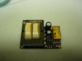
After the components on the bottom were soldered and their leads trimmed as close to the board as possible, the topside components could be added. The main filter capacitor in the supply ended up being 0.2” lead spacing when it should’ve been 0.3” spacing, so it was installed sticking up from the board. That shouldn’t make too much difference as it’s still shorter than the power transformer. Here’s the board with the remainder of components installed (sans protection diode, forgot to bring some!):
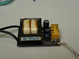
The board was designed to be installed inside devices to be controlled by an external circuit. In order to provide the most versatile mounting options, I placed four large vias in the corners of the boards. These can be used to mount the control board on standoffs if it’s in an enclosure that allows for proper mounting. If not, the holes can be repurposed as one of my favorite methods of providing strain relief for supply and control wires:
The board was brought up on a variac and the 24V supply checked before further testing. No excessive current draw, +24V line at 24 VDC, no ripple with the relay in the off state. 9 VDC was applied to the optoisolator’s source from a 9V battery through a 680 Ohm resistor, and…nothing. On closer observation, a very faint click could be heard from the Aromat telecom relay installed in the board. Usually, you get a notable, pronounced click as the relay transfers. The optoisolator was working as 24 VDC appeared at the relay terminals when the source was powered. Oops! Turns out these Aromat DS2E series relays have polarized coils! Two trace cuts, a solder bridge and a bit of jumper wire later, the relay was clacking loudly as it should, fully transferring its contacts.
The final corrected board accomplishes everything I wanted from this design. It provides greater than 500 V isolation between the power source, control source, and the device being controlled. The traces that parallel the primaries of the power supply transformer can be cut and the primaries connected in series for 240 VAC supply operation. While there is a footprint for DIP style relays, the boards are also usable with external relays. Best of all, the individual boards cost less than $5 USD in prototype quantities and the components that had to be ordered cost less than $1 USD per board! Not a significant cost over plain pad-per-hole protoboard and certainly a lot faster to assemble.
This project is an Open Hardware project; as such, the EAGLE schematic, board, and custom parts files are available on GitHub, along with documentation. Please contact us if you are interested in taking part in a bulk production-size order of these boards. As of the date of writing, all components necessary to build these boards are readily available from several suppliers.
output ports fried
